Communication Receiver Block Diagram:
A Communication Receiver Block Diagram is one whose main function is the reception of signals used for communications rather than for entertainment. It is a radio receiver designed to perform the tasks of low- and high-frequency reception much better than the type of set found in the average household. In turn, this makes the communications receiver useful, in other applications, such as the detection of signals from high-frequency impedance bridges (where it is used virtually as a high-sensitivity tuned voltmeter), signal-strength measurement, frequency measurement and even the detection and display of individual components of a high-frequency wave (such as an FM wave with its many sidebands). It is often operated by qualified people, so that any added complications in its tuning and operation are not necessarily detrimental, as they would be in a receiver to be used by the general public.
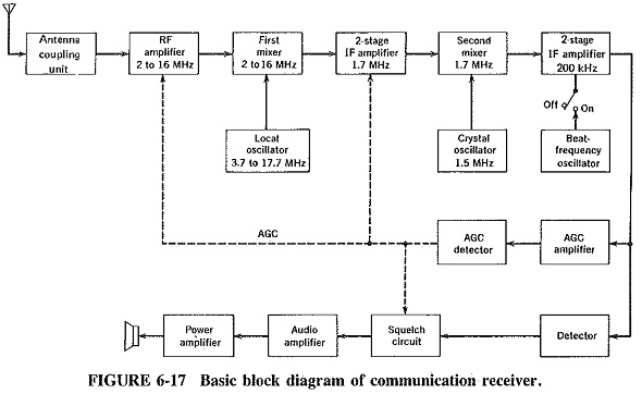
The communications receiver has evolved from the ordinary home receiver, as the block diagram of Figure 6-17 and the photograph of Figure 6-18 demonstrate. Both are superheterodyne receivers, but in order to perform its tasks the Communication Receiver Block Diagram has a number of modifications and added features. These are the subject of this section, in which the strange new blocks of Figure 6-17 will also be discussed.
Extensions of the Superheterodyne Principle:
Some of the circuits found in communications receivers,’ such as tuning indicators and beat-frequency oscillators, may be said to.4)e mere additions, other circuits are really extensions of the superheterodyne principle. Delayed AGC and double conversion are” but two of these circuits. It has been found convenient to subdivide the topic into extensions of the superheterodyne principle and additions to it.
Input stages: It is common to have one, or sometimes even two, stages of RF amplification. Two stages are preferable if extremely high sensitivity and low noise are required, although some complications in tracking are bound to occur. Regardless of the number of input stages, some system of band changing will have, to be used if the receiver is to cover a wide frequency range, as nearly all Communication Receiver Block Diagram do. This is compounded by the fact that the normal variable capacitor cannot be relied upon to cover a frequency ratio much in excess of 2: 1 at high frequencies. Band changing is accomplished in either of two ways by switching in the required RF, mixer and local oscillator coils, or by frequency synthesis. The use of synthesis is a clear favorite in modern receivers.
Fine tuning: As the name implies, fine tuning permits stations transmitting on frequencies very close to each other to be separated, or resolved, by the receiver. This ability is essential in a Communication Receiver Block Diagram. Some good-quality domestic receivers provide an electrical fine-tuning control, using a separate dial. In this method, the local oscillator frequency is varied by means of a trimmer on either side of the main tuning control setting, and in this fashion close stations are separated. Similar results can be achieved with a mechanical vernier control, and indeed this is how fine tuning, or bandspread, used to be provided in communications receivers. These days, the use of frequency synthesis, as in the receiver of Figure 6-18, is almost invariable in commercial communications receivers.
Double conversion Communications receivers and some high-quality domestic AM receivers have more than one intermediate frequency generally two, but sometimes even more. When a receiver has two different IFs, as does the one shown in block diagram form in Figure 6-17, it is then said to be a double-conversion receiver. The first IF is high, several megahertz or even higher, and sometimes not even a fixed frequency. The second IF is quite low, of the order of 1 MHz or even less. After leaving the RF amplifier, the signal in such a receiver is still mixed with the output of a local oscillator. This is similar to the local oscillator of a domestic receiver, except that now the resulting frequency difference is a good deal higher than 455 kHz. The high intermediate frequency is then amplified by the high-frequency IF amplifier, and the output is fed to a second mixer and mixed with that of a second local oscillator. Since the second local oscillator frequency is normally fixed, this could be a crystal oscillator, and in fact very often is, in non-synthesized receivers. The low second intermediate frequency is amplified by an LF IF amplifier and then detected in the usual manner.
Double conversion is desirable in communications receivers. As will be recalled from Section 6-2.3, the intermediate frequency selected for any receiver is bound to be a compromise since there are equally compelling reasons why it should be both high and low. Double conversion avoids this compromise. The high first intermediate frequency pushes the image frequency farther away from the signal frequency and therefore permits much better attenuation of it. The low second IF, on the other hand, has all the virtues of a low fixed operating frequency, particularly sharp selectivity and hence good adjacent-channel rejection.
Please note that the high intermediate frequency must come first. If this does not happen, the image frequency will be insufficiently rejected at the input and will become mixed up with the proper signal, so that no amount of high IF stages will make any difference afterward.
Having two such intermediate frequencies provides a combination of higher image and adjacent-frequency rejection than could be achieved with the simple superheterodyne system. It should be noted that double conversion offers no great advantages for broadcast or other medium-frequency receivers. It is essential for receivers operating in crowded HF and other bands.

