Compensating Winding in DC Machine:
Compensating Winding in DC Machine – It was seen from earlier section, that armature reaction causes the flux density wave to be so badly distorted that when a coil is passing through the region of peak flux densities, the emf induced in it far exceeds the average coil voltage. If this emf is higher than the breakdown voltage across adjacent segments, a sparkover could result which can easily spread over and envelop the whole commutator as the environment near the commutator is always somewhat ionized and conditions are favourable for flashover. The result is complete short circuit of armature. The maximum allowable voltage between adjacent segments is 30-40 V, limiting the average voltage between them to much less than this figure. The choice of the average coil voltage determines the minimum number of commutator segments for its design.
In spite of the above safe design of the commutator there is another factor which can cause severe overvoltages to appear between commutator segments. This is the time variation of the armature reaction and its associated flux owing to sudden changes in machine load.
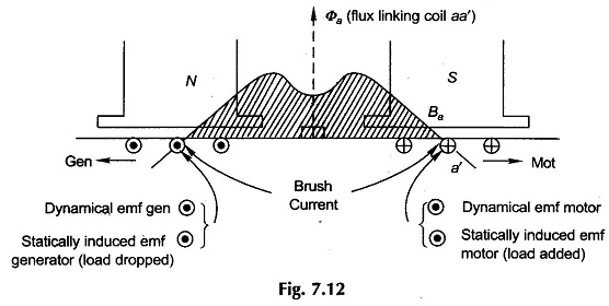
Consider coil aa’ of Fig. 7.12 located midway between the main poles so that the full armature flux/pole, Φa (shaded area), links the coil. If the load on the machine undergoes a fast change, Ia and Φa change accordingly resulting in statically induced emf in the coil proportional to dΦa/dt.. The voltage is over and above the dynamically induced emf in the coil. Worst conditions occur when these two emfs are additive. This happens when load is dropped from a generator or added to a motor. (The reader should verify by application of the right-hand rule and Lenz’s law to coil aa’ of Fig. 7.12.) The only way to remedy this situation is to neutralize the armature reaction ampere-turns by a compensating winding in dc machine placed in slots cut out in pole faces such that the axis of this winding coincides with the brush axis (along which lies the axis of ATa).
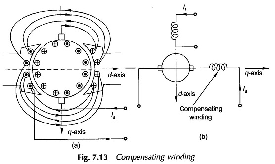
For automatic neutralization of ATa at any current, it is necessary that the compensating winding be series excited with armature current in such a direction as to oppose ATa. The compensating winding appropriately connected is shown schematically in Figs 7.13(a) and (b).
It is found from Fig. 7.13(a) that complete neutralization of the armature mmf is not possible with this arrangement, since the distributions of armature and compensating mmfs are not identical. It is customary to compensate part of the armature mmf directly under the pole shoes. The number of ampere-turns required for this purpose is
The compensating winding in dc machine neutralizes the armature mmf directly under the pole while in the interpolar region, there is incomplete neutralization. Further, the effect of the resultant armature mmf in interpolar region is rendered insignificant because of large interpolar gap. The compensating winding, therefore, practically eliminates the air-gap flux density distortion. The small flux density remaining unneutralized in GNA will be appropriately modified by the interpole windings.
Compensating windings, though expensive, must be provided in machines where heavy overloads are expected or the load fluctuates rapidly, e.g. motors driving steel-mills are subjected to severe duty cycles with rapid changes.

