Construction of Transformer and types of transformer:
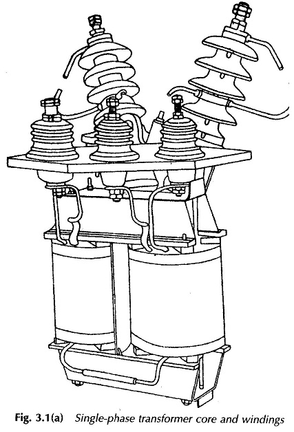
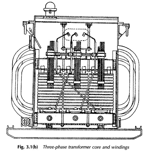
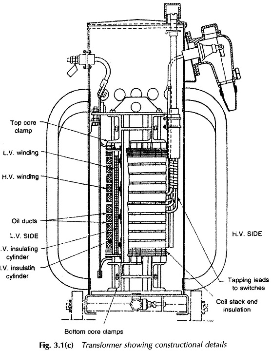
Construction of Transformer is intimately related to the purpose for which these are to be used; winding voltage, current rating and operating frequencies. The construction has to ensure efficient removal of heat from the two seats of heat generation core and windings, so that the temperature rise is limited to that allowed for the class of insulation employed. Further, to prevent insulation deterioration, moisture ingress to it must not be allowed. These two objectives are simultaneously achieved in power transformers, other than those in very small sizes, by immersing the built-up transformer in a closed tank filled with noninflammable insulating oil called transformer oil. To facilitate natural oil circulation and to increase the cooling surface exposed to the ambient, tubes or fins are provided on the outside of tank walls. In large-size transformers tubes may be forced-cooled by air. For still larger installations the best cooling system appears to be that in which the oil is circulated by pump from the top of the transformer tank to a cooling plant, returning when cold to the bottom of the tank. In small sizes the transformers are directly placed in a protective housing or are encased in hard rubber moulding and are air-cooled. Figures 3.1. (a), (b) and (c) show the constructional details of practical transformers.
 Power transformers are provided with a conservative through which the transformer breathes into the atmosphere. The conservative is a smaller-sized tank placed on top of the main tank. This arrangement ensures that surface area of transformer oil exposed to atmosphere is limited so as to prevent fast oxidization and consequent deterioration of insulating properties of the oil.
The magnetic core of a Construction of Transformer is made up of stacks of thin lamination (0.35 mm thickness) of cold-rolled grain-oriented silicon steel sheets lightly insulated with varnish. This material allows the use of high flux densities (1-1.5 T) and its low-loss properties together with laminated construction reduce the core-loss to fairly low values. The lamination are punched out of sheets and the core is then built of these punching. Before building the core, the punched laminations are annealed to relieve the mechanical stresses set in at the edges by the punching process; stressed material has a higher core-loss. Pulse transformers and high-frequency electronic transformers often have cores made of soft ferrites.
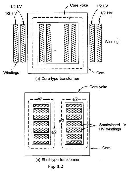
In Construction of Transformer the primary and secondary coils are wound on the core and are electrically insulated from each other and from the core. Two types of cores are commonly employed in practice—core-type and shell-type. In core-type construction shown in Fig. 3.2(a) the windings are wound around the two legs of a rectangular magnetic core, while in shell-type construction of Fig. 3.2(b), the windings are wound on the central leg of a three-legged core. Though most of the flux is confined to a high permeability core, some flux always leaks through the core and embraces paths which partially lie in the air surrounding the core legs on which the coils are wound. This flux which links one of the windings without linking the other, though small in magnitude, has a significant effect on the transformer behavior. Leakage is reduced by bringing the two coils closer. In a core-type transformer this is achieved by winding half low-voltage (LV) and half high-voltage (HV) winding on each limb of the core as shown in Fig. 3.2(a). The LV winding is wound on the inside and HV on outside to reduce the amount of insulation needed. Insulation between the core and the inner winding is then stressed to low voltage.
The two windings are arranged as concentric coils in the Construction of Transformer. In shell-type construction leakage is reduced by subdividing each winding into subsections (wound as pancake coils) and interleaving LV and HV windings as shown in Fig. 3.2(b).
The core-type construction has a longer mean length of core and a shorter mean length of coil turn. This type is better suited for EHV (extra high voltage) requirement since there is better scope for insulation. The shell-type construction has better mechanical support and good provision for bracing the windings. The shell-type transformer requires more specialized fabrication facilities than core-type, while the latter offers the additional advantage of permitting visual inspection of coils in the case of a fault and ease of repair at substation site. For these reasons, the present practice is to use the core-type transformers in large high-voltage installations.
Transformer windings are made of solid or stranded copper or aluminium strip conductors. For electronic transformers, “magnet wire” is normally used as conductor. Magnet wire is classified by an insulation class symbol, A, B, C, F and H, which is indication of the safe operating temperature at which the conductor can be used. Typical figures are the lowest 105 °C for class-A and highest 180 °C for class-H.
In Construction of Transformer the windings of huge power transformers use conductors with heavier insulation (cloth, paper, etc.) and are assembled with greater mechanical support and the winding layers are insulated from each other—this is known as minor insulation for which pressed board or varnished cloth is used. Major insulation, insulating cylinders made of specially selected pressed board or synthetic resin bounded cylinders, is used between LV and core and LV and HV. Insulating barriers are inserted between adjacent limbs when necessary and between coils and core yokes.


