Continuous Balance DVM:
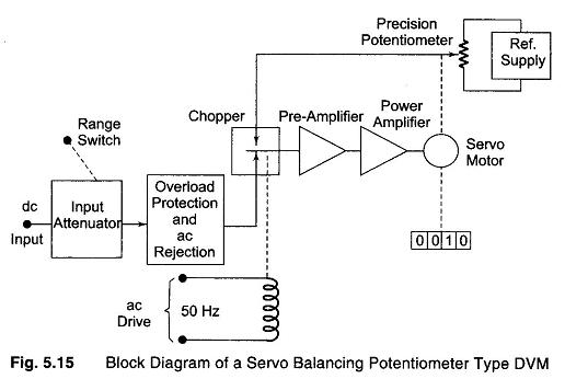
Continuous Balance DVM – The basic block diagram of a servo balancing potentiometer type DVM is shown in Fig. 5.15.
The input voltage is applied to one side of a mechanical chopper comparator, the other side being connected to the variable arm of a precision potentiometer. The output of the chopper comparator, which is driven by the line voltage at the line frequency rate, is a square wave signal whose amplitude is a function of the difference in voltages connected to the opposite side of the chopper. The square wave signal is amplified and fed to a power amplifier, and the amplified square wave difference signal drives the arm of the potentiometer in the direction needed to make the difference voltage zero. The servo-motor also drives a mechanical readout, which is an indication of the magnitude of the input voltage.
This DVM uses the principle of balancing, instead of sampling, because of mechanical movement. The average reading time is 2 s.
3 1/2 – DIGIT
The number of digit positions used in a digital meter determines the resolution. Hence a 3 digit display on a DVM for a 0 – 1 V range will indicate values from 0 – 999 mV with a smallest increment of 1 mV.
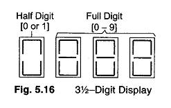
Normally, a fourth digit capable of indicating 0 or 1 (hence called a Half Digit) is placed to the left. This permits the digital meter to read values above 999 up to 1999, to give overlap between ranges for convenience, a process called over-ranging. This type of display is called a 3½ digit display, shown in Fig. 5.16.
Resolution and Sensitivity of Digital Meters:
Resolution:
If n= number of full digits, then resolution (R) is 1/10n.
The resolution of a DVM is determined by the number of full or active digits used,
Sensitivity of Digital Meters:
Sensitivity is the smallest change in input which a digital meter is able to detect. Hence, it is the full scale value of the lowest voltage range multiplied by the meter’s resolution.


