Control Techniques for Electric Drives Articles:
Introduction Control Techniques in Electric Drives: An electric drive is a well established industrial drive as it has several advantages and special features. Its Control Techniques consists in starting, speed control, braking and speed reversal, and also maintaining the drive conditions … (Read More)
Features of Electric Drive System: Before applying advantageously the control principles to electric drive systems to adjust or improve their behaviour as a special case of control problem, it is necessary to have a knowledge of the specific Features of Electric … (Read More)
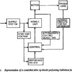
Block Diagram of Electric Drive System: It is normal practice in control engineering to represent a control system by means of a Block Diagram of Electric Drive System, with a systematic connection of blocks in the direction of signal flow, showing … (Read More)
Signal Flow Graph of DC Motor in Electric Drive System: The Signal Flow Graph of DC Motor in Electric Drive System block diagram representation discussed above is adequate only for simple systems having components with one input and one output. When … (Read More)
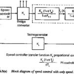
Closed Loop Control of DC Motor: The dynamic behaviour of a system is described by a set of differential equations. On many occasions the solution of these equations requires the evaluation of convolution integrals … (Read More)
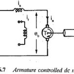
Transfer Function of Armature Controlled DC Motor: The speed of a dc motor can be controlled by varying the voltage applied to the armature of a dc motor. A separately excited dc motor with variable armature voltage finds application as a … (Read More)
Transfer Function of a Field Controlled DC Motor: The speed of a dc motor can be varied by varying the field current. The speed can be increased beyond base speed by decreasing the field current. The Fig. 6.8(c&d) shows the Transfer Function … (Read More)
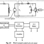
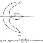
Ward Leonard Drive Transfer Function: In the classical Ward Leonard Drive Transfer Function, the dc drive motor having constant excitation is supplied from a variable voltage generator, as shown in Fig. 6.9. The generator is driven at constant speed. The field … (Read More)
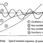
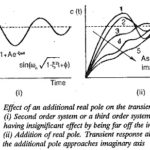
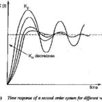
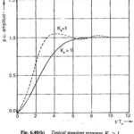
Transient Response of Closed Loop Drive System: The Transient Response of Closed Loop Drive System is of fundamental importance and must be investigated in detail. The time response of a system to specified inputs gives information with respect to the following … (Read More)
Frequency Response Transfer Function: The previous sections- show that with the time response of a system, even though it is a direct method of analysis, the adjustment of the parameters to give a satisfactory time domain performance is rather tedious particularly … (Read More)
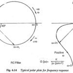
Polar Plot for Frequency Response: One of them is the Polar Plot for Frequency Response representation. The transfer function in the frequency domain is obtained by substituting jω for s as complex function of ω. It is separated into real and … (Read More)
Correlation Between Frequency and Transient Response: As has been stated, the use of frequency response for the design of control systems requires a Correlation Between Frequency and Transient Response. Time response specifications are available for the performance of a system. These … (Read More)
Stability Control Drives: The concept of stability is very well known. By the term stability one implies the ability of a system to return to its original position or attain a new steady-state condition when there is some disturbance or change … (Read More)
Routh Hurwitz Criterion: The Routh Hurwitz Criterion states that the system is stable if the Routh table has no negative elements in the first column. The roots of the characteristic polynomial are negative if they are real or contain negative real … (Read More)
Nyquist Criterion: This stability criterion enables one to establish the stability of a system using a graphical procedure in the frequency domain. Here also there is no necessity for the evaluation of the roots of the characteristic equation. … (Read More)
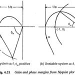
Relative Stability from the Nyquist Plot: The considerations discussed above provide information about the absolute stability of the system, i.e., whether the system is stable or not. An equally important system behaviour to be … (Read More)
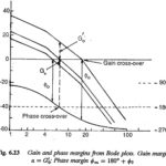
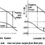
Stability from Bode Plot of Open Loop Transfer Function: The Nyquist criterion details how the open loop polar plot can be used for establishing. the stability of a closed loop system. In terms of phase and gain margins it has been … (Read More)
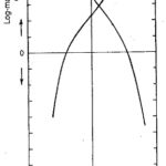
Stability from Log Magnitude Angle Diagram: Yet another way of portraying the frequency response is to draw a curve showing the Log Magnitude Angle Diagram in decibels on the Y-axis and phase angle on the x-axis. The frequency ω is varied … (Read More)
Root Locus Plot: In the electrical drives employing closed loop control techniques, it is often necessary to investigate the effects of changing the parameters of the system on its stability. The drive motor used itself has several parameters and time constants … (Read More)
Control System Performance: From the foregoing discussion on control systems it can be seen that the behaviour of the control systems can be specified, based on several time domain specifications. To provide a basis for comparison of several types of control … (Read More)
Methods of Compensation in Control System: The Different Methods of Compensation in Control System are Cascade Compensation Feedback Compensation Load Circuit Compensation Input Circuit Compensation A drive system having closed loop control may not be satisfactory with regard to its stability characteristics, speed of response and … (Read More)
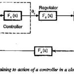
Controller Design Frequency Response: The Controller Design Frequency Response (or root locus) alters or reshapes the frequency response (or root locus) of the original system to the desired one. Thus the ideal goal of compensation is to achieve a control system … (Read More)
Magnitude Optimum: The design of a controller based on the principle Magnitude Optimum that it allows all the frequencies to pass through in a similar way for a simple system is shown in Fig. 6.31. The system has an input R(s) and output … (Read More)
Phase Margin Optimum: The method can be based on the phase margin in which the controller is designed to provide a minimum phase margin. The design makes use of Bode plots. The ratio of time constants can be decided depending upon … (Read More)
Controller Transfer Function: While a Controller Transfer Function is designed to improve the behavior of a given control system in practice it is very difficult to realize such a controller because of the availability of components. The actual time constant of … (Read More)
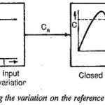
Design of Controllers for Linearly Varying Inputs: The Design of Controllers for Linearly Varying Inputs discussed in the foregoing sections are for the step input. The performance has been found to depend very much upon the value of integration time in … (Read More)
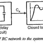
Exponential Variation of the Input to the Controller: The linear Exponential Variation of the input to the Controller, discussed in the foregoing section, is too involved to achieve by means of circuits using discrete elements. On the other hand a simple … (Read More)
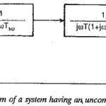
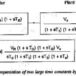
Uncompensated Large Time Constants: It is possible to compensate only one Uncompensated Large Time Constants using a PI controller. A PID controller is used to compensate for two large time constants. On technical grounds, compensation of more than two constants using … (Read More)
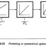
Symmetrical Optimum: Sometimes automatic control systems contain integrating also besides first order delay elements, proportional elements and deadzones. Such a system when compensated on the basis of magnitude optimum discussed in the previous sections will become oscillatory with zero … (Read More)