Converters for Electric Motors Articles:
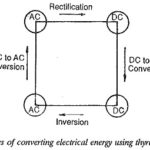
Electric Converter: The speed of a dc motor can be varied by varying the armature voltage or the field current, for which a variable dc supply is required. The speed of an ac motor, on the other hand, … (Read More)
Phase Controlled Line Commutated Converters: In these Phase Controlled Line Commutated Converters, the commutation voltage, i.e. the voltage required to transfer current from one thyristor to the other, is provided by the supply lines to which the converter is connected. The … (Read More)
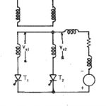
Two pulse mid point converter: Two pulse mid point converter are, in general, single phase converters. The pulse number of the converter indicates the frequency of the ripple voltage superimposing the average dc voltage at the terminals. The schematic of a … (Read More)
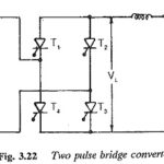
Two pulse bridge converter: A two pulse bridge converter is achieved as shown in Fig. 3.22 from two midpoint converters. They are connected in series on the dc side and in parallel on the ac side, It is also a single … (Read More)
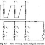
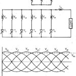
Three pulse midpoint converter: These are basically three-phase converters, and are very popular because a 3-phase supply is readily available. 3-phase converters have a greater power capability than single phase converters. With these converters the pulse number of the output voltage … (Read More)
Six pulse midpoint converter: The converter transformer converts the existing three phase system to a six phase one, since it has six secondary windings. The Six pulse midpoint converter connections are shown in Fig. 3.32. A thyristor having maximum voltage can go … (Read More)
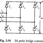
Six pulse bridge converter: The conduction time of a thyristor in a six pulse connection can be increased when the converter is obtained by a series or parallel connection of two three-pulse midpoint converters. A Six pulse bridge converter is obtained … (Read More)
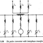
Six Pulse Converter with Interphase Transformer: The basic connection of a Six Pulse Converter with Interphase Transformer is shown in Fig. 3.38. This is obtained by connecting two three pulse converters in parallel on the dc side. The interphase transformer absorbs … (Read More)
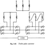
Twelve pulse converter: It is clear from the preceding discussion that increasing the pulse number to six greatly improves the performance of the converter. The ac line current has only odd harmonics and the value of g increases to 0.96, indicating … (Read More)
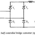
Two pulse half controlled bridge converter: A Two pulse half controlled bridge converter is obtained by connecting a two pulse controlled midpoint converter in series with an uncontrolled one, as shown in Fig. 3.45. The controlled converter has thyristors T1 and T2 … (Read More)
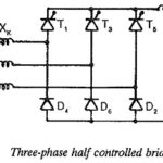
Three phase half controlled bridge circuit: This is obtained by a series connection of a 3 pulse controlled converter and a 3 pulse uncontrolled one. The three arms of the former consist of thyristors and the three arms of the latter … (Read More)
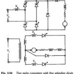
Two pulse converters with freewheeling diode: One quadrant converters can also be obtained by connecting a free wheeling diode across the load terminals. This is possible with both midpoint and bridge converters, as shown in Fig. 3.54. The Two pulse converters … (Read More)
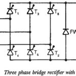
Bridge Rectifier Circuit Diagram with freewheeling diode: A 6 pulse Bridge Rectifier Circuit Diagram with freewheeling diode across the load terminals is shown in Fig. 3.58. As has already been explained, the diode participates in conduction only when the instantaneous load … (Read More)
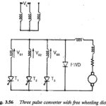
Three pulse converter with freewheeling diode: A Three pulse converter with freewheeling diode across the load terminals is depicted in Fig. 3.56. The diode is meant to provide an alternative path for the load current, which would otherwise have flown through … (Read More)
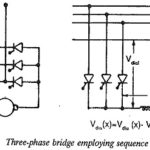
Sequence control of Converters: We have shown that fully controlled converters take lagging reactive power from the mains. This requirement is less in half controlled converters and converters with a freewheeling diode, which however do not … (Read More)
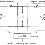
Four Quadrants Converters: The converters described in the previous sections are suitable either for one quadrant or two quadrant operation. In the former case stepless speed control is possible by changing the applied voltage. There is no … (Read More)
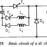
DC Chopper: DC Chopper are mainly dc to dc single stage conversion devices which provide a variable voltage on the load side when fed from a constant dc voltage source. The commutation of the current from the thyristors cannot be achieved … (Read More)
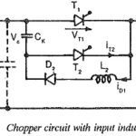
Chopper Circuit with Input Inductance: The preceding discussion of the chopper assumes ideal conditions and does not consider the effects of inductances in series with the thyristors. With choppers of large power, the leads connecting the Chopper Circuit to the supply … (Read More)
Performance of Chopper in Steady State Condition: Assuming Steady State Condition of the chopper, we have during TON The solution of Eq. 3.89 is where Io is the current at the starting of TON. At TON = aT, the current is when the thyristor … (Read More)
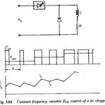
Methods of Controlling Chopper Circuit: The basic principle of control of a Chopper Circuit is the effective change of the value of the time ratio. This is done in two ways: 1.Time ratio control 2.Current limit control In the former, the ratio TON/T is … (Read More)
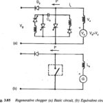
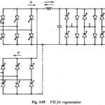
Regenerative Braking: Sometimes the energy of the load may have to be fed to the supply system. A Chopper in this mode is called regenerative. The chopper working as a switch is connected across the load, which is normally a dc … (Read More)
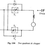
Two Quadrant Chopper: Sometimes a chopper may be required to provide a two quadrant operation by retaining the current direction in both motoring and braking modes. Such a Two Quadrant Chopper is shown in Fig. 3.86, and its waveforms in Fig. … (Read More)
Selection of Ratings of Devices of a Chopper Converter: Chopper Converter – The waveforms of currents and voltages are useful in deciding the ratings of devices. The main thyristor carries the load current. Superimposed on this there is a current pulse … (Read More)
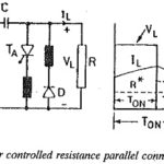
Chopper Controlled Resistance: By interrupting the flow of current through a resistance R in a periodic fashion using a switch, the value of resistance can be effectively varied. The interruption of the current can be accomplished by means of a dc … (Read More)
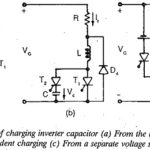
Charging a Capacitor in Inverter: Inverters are static power converters for converting dc to ac. By controlling the conducting periods of the thyristors it is possible to obtain variable frequency at the output terminals of … (Read More)
Three Phase Inverter: The variable frequency required for the speed control of three phase ac motors is obtained from a Three Phase Inverter. To avoid magnetic saturation and to obtain constant flux conditions in the machine, the voltage fed to the … (Read More)
Features of Variable Voltage Inverters: The inverter has an impressed dc voltage. The output voltage of the inverter is decided by the firing and duration of the thyristors. The conduction of the thyristors can be either 180° or 120°, depending upon … (Read More)
Current Source Inverter for Feeding Three Phase Motors: In these type of Current Source Inverter, the controlled quantity is the current in the dc link. The current from the dc source remains constant at the controlled value, irrespective of the load … (Read More)
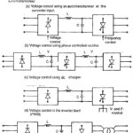
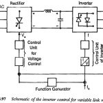
Voltage Control Techniques for Inverters: It has already been mentioned that Inverter Control providing a variable frequency supply to three phase motors should be capable of providing a variable voltage. This is required to avoid saturation and ensure operation at constant … (Read More)
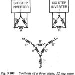
Harmonic Reduction: The output voltage waveform of an inverter is non-sinusoidal. It contains a rich harmonic content. The Harmonic Reduction cause additional losses and torque pulsations if a three phase motor is used as a load. These torque pulsations pose a … (Read More)
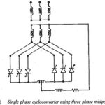
Cycloconverter: A variable frequency supply for feeding a three phase motor can be obtained from a cycloconverter which operates on a 50 Hz supply and provides a variable frequency supply at the output (Fig. 3.105). These are single stage frequency conversion … (Read More)
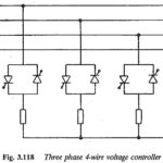
Three Phase AC Voltage Controller: To control the current and voltage of three phase loads, Three Phase AC Voltage Controller are required. The single phase controller described previously can be introduced singly in each phase or line, to form a three … (Read More)
Field Oriented Control of Induction Motor: In the slip controlled drives using VSI or CSI discussed in the foregoing sections, the stator voltage or stator current is controlled using slip frequency. They are controlled in magnitude only. The stator current control … (Read More)
