Coupled Circuit Articles:
Coupled Circuits Definition: Two circuits are said to be ‘coupled’ when energy transfer takes place from one circuit to the other when one of the circuits is energized. There are many types of Coupled Circuits like conductive coupling as shown by … (Read More)
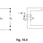
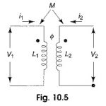
Mutual Inductance of Coupled Circuits: A voltage is induced in a coil when there is a time rate of change of current through it. The inductance parameter L, is defined in terms of the voltage … (Read More)
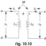
Dot Convention in Coupled Circuits: Dot Convention in Coupled Circuits is used to establish the choice of correct sign for the mutually induced voltages in coupled circuits. Circular dot marks and/or special symbols are placed at one end of each of two … (Read More)
Coefficient of Coupling: The amount of coupling between the inductively coupled coils is expressed in terms of the coefficient of coupling, which is defined as where M = mutual inductance between the coils L1 = self inductance of the first coil, and L2 = self … (Read More)
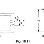
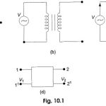
Ideal Transformer on Load: Transfer of energy from one circuit to another circuit through mutual induction is widely utilized in power systems. This purpose is served by Ideal Transformer on Load. Most often they transform energy at one voltage (or current) … (Read More)
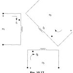
Inductively Coupled Circuits: Inductively coupled multi-mesh circuits can be analysed using Kirchhoff s laws and by loop current methods. Consider Fig. 10.17, where three coils are inductively coupled. For such a system of inductors we can define a inductance matrix L as where … (Read More)
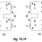
Series Connection of Coupled Inductors: Let there be two inductors connected in series, with self inductances L1 and L2 and mutual inductance of M. Two kinds of Series Connection of Coupled Inductors are possible; series aiding as in Fig. 10.19(a), and … (Read More)
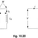
Parallel Connection of Coupled Coils: Consider two inductors with self inductances L1 and L2 connected parallel which are mutually coupled with mutual inductance M as shown in Fig. 10.20. Let us consider Fig. 10.20(a) where the … (Read More)
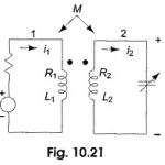
Single Tuned Circuit: Consider the Single Tuned Circuit in Fig. 10.21. A tank circuit (i.e. a parallel resonant circuit) on the secondary side is inductively coupled to coil (1) which is excited by a source, υi. Let Rs be the source … (Read More)
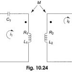
Doubled Tuned Coupled Circuits: Figure 10.24 shows a Doubled Tuned Coupled Circuits involving two series resonant circuits. For the circuit shown in the figure, a special case where the primary and secondary resonate at the same frequency ωr, is considered here, i.e. The two … (Read More)
Magnetic Circuit Analysis: The presence of charges in space or in a medium creates an electric field, similarly the flow of current in a conductor sets up a magnetic field. Electric field is represented by electric flux … (Read More)
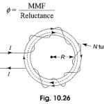
Series Magnetic Circuit: A series magnetic circuit is analogous to a series electric circuit. Kirchhoff s laws are applicable to magnetic circuits also. Consider a ring specimen having a magnetic path of l meters, area of cross-section (A)m2 with a mean … (Read More)
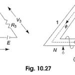
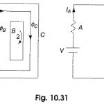
Difference Between Electric Circuit and Magnetic Circuit: A Difference Between Electric Circuit and Magnetic Circuit are shown in Figs. 10.27(a) and (b) respectively. Figure 10.27(a) represents an electric circuit with three resistances connected in series, the dc source E drives the current … (Read More)
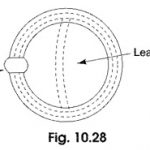
Magnetic Leakage and Fringing: Figure 10.28 shows a magnetized iron ring with a narrow air gap, and the flux which crosses the gap can be regarded as useful flux. Some of the total flux produced by … (Read More)
Parallel Magnetic Circuit: We have seen that a series magnetic circuit carries the same flux and the total mmf required to produce a given quantity of flux is the sum of the mmf’ s for the separate parts. In a Parallel … (Read More)