Current Regulated Voltage Source Inverter:
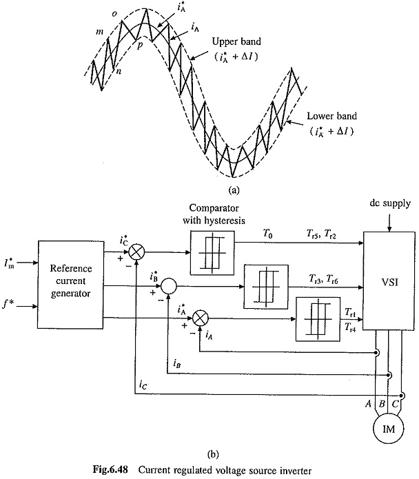
Current Regulated Voltage Source Inverter operates with current controlled PWM. In current controlled pulse-width modulation, machine phase current is made to follow a sinusoidal reference current within a hysteresis band. Fig. 6.48(a) shows a sinusoidal reference current i*A = Im sin ωt. Two bands, separated from i*A by an amount Δl, are shown in the figure. Switching in the inverter is carried out such that the actual motor current iA remains within these two bands. For this voltage source inverter of Fig. 6.37(a) is employed. In this inverter phase A current iA is shaped by transistors Tr1 and Tr4. When Tr1 is on (Tr4 is off), phase A is connected to.the positive terminal of dc source, hence the rate of change of current iA will be positive and when Tr4 is on (Tr1 is off), phase A is connected to negative terminal of the dc source, hence rate of change of current iA will be negative. In Fig. 6.48(a) current iA is falling along the path mn when Tr4 is on. When iA reaches the lower band at n, Tr4 is turned off and Tr1 is turned on. This makes rate of change of iA to be positive and it rises along the path no. When iA reaches the upper band at 0, Tr1 is turned off and Tr4 is turned on. This makes rate of change of iA to be negative and it falls along op. This way actual current iA is constraint to remain within two hysteresis bands. Reference current for phases B and C are chosen to be i*B = Im sin(ωt -120∘) and i*C = Im sin(ωt – 240∘) and by controlling respective transistors iB and iC are made to follow i*B and i*C within hysteresis bands.
When the band is small, motor currents will be nearly sinusoidal. As the band reduces, harmonic content in phase currents reduces but then switching frequency increases. Thus, inverter with fast switching devices will have lower harmonic content.
Fig. 6.48(b) gives block diagram of Current Regulated Voltage Source Inverter. Based on current amplitude command I*m and frequency command f*, reference current generator generates sinusoidal reference currents i*A, i*B and i*C. These reference currents are compared with respective motor currents, iA, iB and iC in comparators with hysteresis to generate base drives for switches.
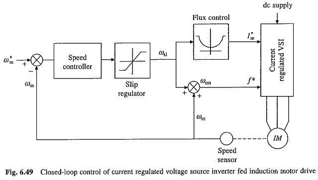
Since the magnitude and waveforms of motor currents are independent of changes in motor impedance and source voltage, the inverter essentially operates as a current source inverter. The closed-loop speed control scheme of CSI drive (Fig. 6.47) is therefore used for Current Regulated Voltage Source Inverter drive also and is shown in Fig. 6.49. A servo drive for closed-loop position control is obtained by adding a position loop around the speed loop in Fig. 6.49.
Although Current Regulated Voltage Source Inverter operates as a CSI, it does not use large dc inductor and filter capacitors, hence it has lower weight, volume and cost and faster dynamic response. This drive has applications in servo control systems.

