Current Series Feedback Amplifier Circuit:
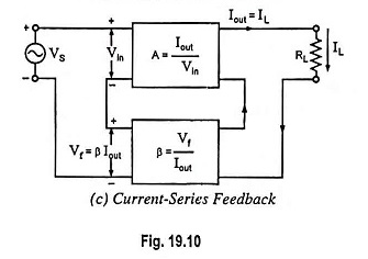
Current Series Feedback Amplifier Circuit is also known as series-derived series fed feedback. In such a feedback circuit, a part of the output current is made to develop a voltage proportional to the output current and supplied back in series with the input, as shown in Fig. 19.10 (c). Since feedback network is in series with the amplifier on the output end as well as on the input end, both input and output impedances are increased with negative feedback.
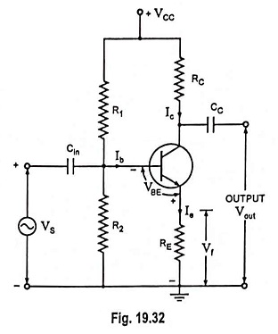
The current feedback can be obtained by removing the bypass capacitor across the emitter resistor RE, as shown in Fig. 19.32 in case of CE amplifier. The emitter resistance RE provides the negative current feedback. The current Ie flowing through resistor RE produces a voltage drop IeRE across emitter resistance RE. This voltage is fed back to the input and opposes the input signal as it is in opposition. This negative voltage feedback is proportional to collector current because Ie ≈ Ic. Thus negative Current Series Feedback Amplifier is provided.
Circuit Analysis:
When an input signal is applied, the resulting collector Ic develops output voltage across the collector load and emitter current Ie develops ac voltage equal to IeRE or IcRE (Ie ≈ Ic) across the emitter.
Thus input voltage to amplifier, which is equal to Vbe, is given as
Thus
Now voltage gain with feedback,
So effective voltage gain with negative current feedback is given by the expression Af = RC/RE. So gain also depends upon the collector load RC. If RC depends upon the frequency i.e., if RC is reactive then there will be distortion in the output.
Applications:
Such a negative feedback is widely employed in practical amplifiers such as in public address systems, record-players, tape recorders, stereo-amplifiers etc. Sometimes, only a part of the emitter resistance is bypassed so that the amplifier gain is not much reduced, and at the same time advantages of negative feedback are achieved.


