Cut Set Matrix and Tree Branch Voltages:
A Cut Set Matrix is a minimal set of branches of a connected graph such that the removal of these branches causes the graph to be cut into exactly two parts. The important property of a Cut Set Matrix is that by restoring anyone of the branches of the cut-set the graph should become connected. A Cut Set Matrix consists of one and only one branch of the network tree, together with any links which must be cut to divide the network into two parts.
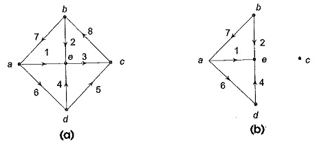
Consider the graph shown in Fig. 2.19 (a).
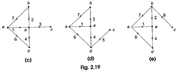
if the branches 3, 5 and 8 are removed from the graph, we see that the connected graph of Fig. 2.19 (a) is separated into two distinct parts, each of which is connected as shown in Fig. 2.19 (b). One of the parts is just an isolated node. Now suppose the removed branch 3 is replaced, all others still removed. Figure 2.19 (c) shows the resultant graph. The graph is now connected. Likewise replacing the removed branches 5 and 8 of the set { 3, 5, 8} one at a time, all other ones remaining removed, we obtain the resulting graphs as shown in Figs 2.19 (d) and (e). The set formed by the branches 3, 5 and 8 is called the cut-set of the connected graph of Fig. 2.19 (a).
Cutset Matrix Concept:
A Cutset Matrix Concept is oriented by arbitrarily selecting the direction. A cut-set divides a graph into two parts. In the graph shown in Fig. 2.20, the cut-set is {2, 3}. It is represented by a dashed line passing through branches 2 and 3. This Cutset Matrix Concept separates the graph into two parts shown as part-1 and part-2. We may take the orientation either from part-1 to part-2 or from part-2 to part-1.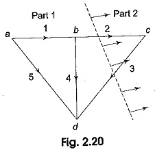
The orientation of some branches of the cut-set may coincide with the orientation of the cut-set while some branches of the cut-set may not coincide. Suppose we choose the orientation of the cut-set {2, 3} from part-1 to part-2 as indicated in Fig. 2.20, then the orientation of branch 2 coincides with the cut-set, whereas the orientation of the branch 3 is opposite.
KCL for Cut–Sets:
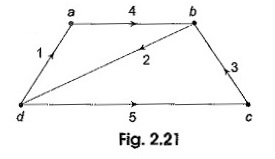
KCL is also applicable to a cut-set of a network. For any lumped electrical network, the algebraic sum of all the cut-set branch currents is equal to zero. While writing the KCL equation for a cut-set, we assign positive sign for the current in a branch if its direction coincides with the orientation of the cut-set and a negative sign to the current in a branch whose direction is opposite to the orientation of the cut-set. Consider the graph shown in Fig. 2.21.
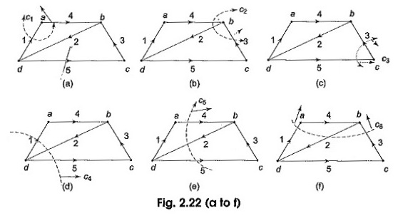
It has five branches and four nodes. The branches have been numbered 1 through 5 and their orientations are also marked. The following six cut-sets are possible as shown in Fig. 2.22 (a)-(f).
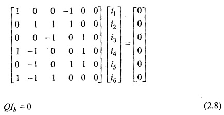
Applying KCL for each of the cut-set we obtain the following equations. Let i1,i2,….i6 be the branch currents.
These equation can be put into matrix form as
where the matrix Q is called augmented cut set matrix of the graph or all cut set matrix of the graph. The matrix 4 is the branch-current vector.
The all cut set matrix can be written as Q = [qij].
where qij is the element in the ith row and jth column. The order of Q is number of cut-sets X number of branch as in the graph.
Fundamental Cut Set Matrix:
Observe the set of equation 2.7 in Section 2.8.2 with respect to the graph in Fig. 2.22. Only first three equations are linearly independent, remaining equations can be obtained as a linear combination of the first three. The concept of fundamental cut-set (f-cut-set) can be used to obtain a set of linearly independent equations in branch current variables. The f-cut-sets are defined for a given tree of the graph. From a connected graph, first a tree is selected, and then a twig is selected. Removing this twig from the tree separates the tree into two parts. All the links which go from one part of the disconnected tree to the other, together with the twig of the selected tree will constitute a cut-set. This cut-set is called a fundamental cut-set or f-cut-set or the graph. Thus a fundamental cut-set of a graph with respect to a tree is a cut-set that is formed by one twig and a unique set of links. For each branch of the tree, i.e. for each twig, there will be a f-cut-set. So, for a connected graph having n nodes, there will be (n – 1) twigs in a tree, the number off-cut-sets is also equal to (n — 1).
Fundamental cut-set matrix Qf is one in which each row represents a cut-set with respect to a given tree of the graph. The rows of Q1 correspond to the fundamental cut-sets and the columns correspond to the branches of the graph.
Tree Branch Voltages and f-Cut-Set Matrix
From the cut set matrix the branch voltages can be expressed in terms of tree branch voltages. Since all tree branches are connected to all the nodes in the graph, it is possible to trace a path from one node to any other node by traversing through the tree-branches.
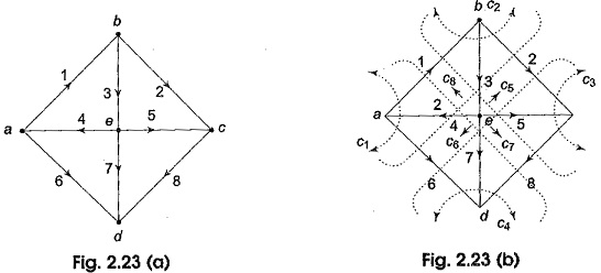
Let its consider Example 2.6, there are eight branches. Let the branch voltages be V1,V2,….V8. There are, four twigs, let the twig voltages be Vt3,Vt4,Vt5 and Vt7 for twigs 3, 4, 5 and 7 respectively.
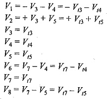
We can express each branch voltage in terms of twig voltages as follows.
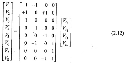
The above equations can be written in matrix form as
The first matrix on the right hand side of Eq. 2.12 is the transpose of the f-cut-set matrix Qf given in Eq. 2.11 in Ex. 2.6. Hence, Eq. 2.12 can be written as Vb=QTfVt. ————— (2.13)
Where Vb is the column matrix of branch-voltages Vt is the column matrix of twig voltages corresponding to the selected tree and QTf in the transpose off-cut-set matrix.
Equation 2.13 shows that each branch voltage can be expressed as a linear combination of the tree-branch voltages. For this purpose fundamental cut set (f-cut-set) matrix can be used without writing loop equations.
