Data Transmission:
A data transmission system can be described simply in terms of three components, the transmitter (also called the source), the transmission path (usually referred to as the channel, but sometimes as the line), and the receiver (usually called the sink).
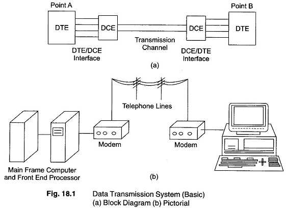
It is easier to think of a data transmission system between points A and B (Fig. 18.1) in terms of the universal seven part data circuit, which consists of the following:
- The data terminal equipment/transducer (DTE) at point A
- The interface between the DTE and the data circuit terminating equipment (DEC) at point A
- The DCE at point A
- The transmission channel between points A and B
- The DCE at point B
- The DCE-DTE interface at point B
- The DTE at point B
The DTE is the source, the sink or both in the system. It transmits and/or receives data by utilising the DCE and data transmission channel. The DTE could be a CRT or teletype terminal, transducer, PC, printer, processor for large main frame computers, or any other device that can transmit and receive data.
The whole purpose of data transmission system is to transmit useful information between points A and B, the information may be used directly by the DTE or the DTE may process or display the information for use by a human operator.
The DCE and the transmission channel perform the function of moving the data from points A to B. In general, they do not know the content of the information transmitted.
The data transmission system is concerned only with the correct transmission of the information given to it, and system does not operate on the content of the information at all. The information received is identical to the information transmitted.
Protocol is the name given to the hardware and software rules and procedures for making sure that transmission errors are detected. The basic elements of a communications protocol are a set of symbols, called a character set, a set of rules for the sequence and timing of messages constructed from the character set, the procedures for determining when an error has occurred in the transmission and how to correct it. The character set consists of a subset which is the signal information (usually called printing characters), and another subset which conveys control information (usually called control characters). There is a correspondence between each character and a group of symbols on the transmission channel.
The set of rules to be followed by the sender and receiver gives the meaning, permissible sequence, and time relationships of the control characters and messages formed from the symbols. The error detection and correction procedure allows for the detection of, and orderly recovery from, errors caused by factors outside the control of the terminal at either end.
The protocol may be as simple as transmitting an extra bit of information in each character to detect errors, or some complex system.
The basic concept of data transmission is the transfer of information from one location to another. In contrast to analog signals which have an infinite number of voltage levels, digital signal information is binary (having two levels). A binary level is called a Bit. A selective arrangement of seven bits provide 27 (128) distinct character combinations, or 128 bytes. The ASCII code is an excellent example of such an arrangement. It is used for the transmission of numbers, alphanumeric characters and miscellaneous information.
For uniform flow of data, the following important points to be agreed upon by the sender and the receiver.
- The nominal rate of transmission (or how many bits are to be emitted per second by the sender).
- The specified information code, providing a one to one mapping ratio of the information to the bit pattern and vice versa.
- A particular scheme by which each bit can be positioned properly, within a byte, by the receiver of the data (in the case of bit-serial transmission).
- A protocol (handshaking) sequence necessary to ensure an orderly flow of information.
