What is Digital Storage Oscilloscope (DSO)?:
Digital Storage Oscilloscope are available in processing and non-processing types. Processing types include built in computing power, which takes advantage of the fact that all data is already in digital form.
The inclusion of interfacing and a microprocessor provides a complete system for information acquisition, analysis and output. Processing capability ranges from simple functions (such as average, area, rms, etc.) to complete Fast Fourier Transform (FFT) spectrum analysis capability.
(Units with built in hard copy plotters are particularly useful, since they can serve as digital scope high speed recorders, tabular printers and X-Y plotters, all in one unit, with computing power and an 8 1/2″ x 11″ paper/ink printout.)
Non-processing digital scopes are designed as replacements for analog instruments for both storage and non-storage types. Their many desirable features may lead to replace analog scopes entirely (within the Bandwidth range where digitization in feasible).
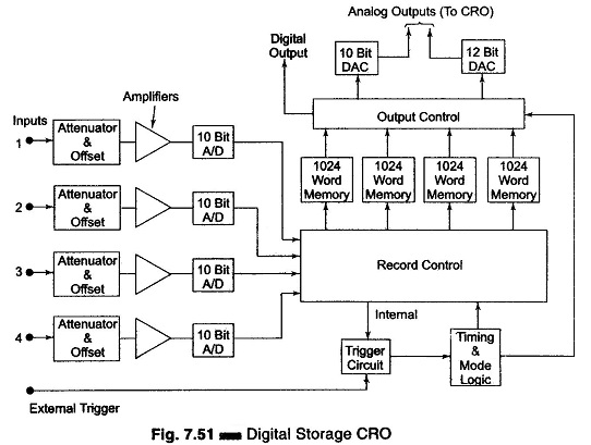
The basic principle of a digital scope is given in Fig. 7.51. The scope operating controls are designed such that all confusing details are placed on the back side and one appears to be using a conventional scope. However, some digital scope panels are simpler also, most digital scopes provide the facility of switching selectable to analog operation as one of the operating modes.
The basic advantage of digital operation is the storage capability, the stored waveform can be repetitively read out, thus making transients appear repetitively and allowing their convenient display on the scope screen. (The CRT used in Digital Storage is an ordinary CRT, not a storage type CRT.)
Furthermore, the voltage and time scales of display are easily changed after the waveform has been recorded, which allows expansion (typically to 64 times) of selected portions, to observe greater details.
A cross-hair cursor can be positioned at any desired point on the waveform and the voltage/time values displayed digitally on the screen, and/or readout electrically.
Some scopes use 12 bit converters, giving 0.025% resolution and 0.1% accuracy on voltage and time readings, which are better than the 2-5% of analog scopes.
Split screen capabilities (simultaneously displaying live analog traces and replayed stored ones) enable easy comparison of the two signals.
Pretrigger capability is also a significant advantage. The display of stored data is possible in both amplitude versus time and X-Y modes. In addition to the fast memory readout used for CRT display, a slow readout is possible for producing hard copy with external plotters.
When more memory than the basic amount (typically 4096 points/words) is needed, a magnetic disk accessory allows expansion to 32,000 points.
All Digital Storage Oscilliscope scopes are limited in bandwidth by the speed of their A/D converters. However, 20 MHz digitizing rates available on some scopes yield a 5 MHz bandwidth, which is adequate for most applications.
Consider a single channel of Fig. 7.51. The analog voltage input signal is digitized in a 10 bit A/D converter with a resolution of 0.1% (1 part in 1024) and frequency response of 25 kHz. The total digital memory storage capacity is 4096 for a single channel, 2048 for two channels each and 1024 for four channels each.
The analog input voltage is sampled at adjustable rates (up to 100,000 samples per second) and data points are read onto the memory. A maximum of 4096 points are storable in this particular instrument. (Sampling rate and memory size are selected to suit the duration and waveform of the physical event being recorded.)
Once the sampled record of the event is captured in memory, many useful manipulations are possible, since memory can be read out without being erased.
If the memory is read out rapidly and repetitively, an input event which was a single shot transient becomes a repetitive or continuous waveform that can be observed easily on an ordinary scope (not a storage scope). The digital memory also may be read directly (without going through DAC) to, say, a computer where a stored program can manipulate the data in almost any way desired.
Pre-triggering recording allows the input signal preceding the trigger points to be recorded. In ordinary triggering the recording process is started by the rise of the input (or some external triggering) above some preset threshold value.
As in digital recorder, Digital Storage Oscilloscope can be set to record continuously (new data coming into the memory pushes out old data, once memory is full), until the trigger signal is received; then the recording is stopped, thus freezing data received prior to the trigger signal in the memory.
An adjustable trigger delay allows operator control of the stop point, so that the trigger may occur near the beginning, middle or end of the stored information.
Commercial DSO:
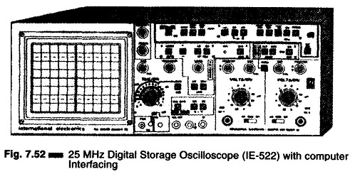
IE-522 shown in illustration Fig. 7.52, is a 25 MHz analog digital storage dual trace four display oscilloscope with computer interface.
The 1E-522 Digital Storage Oscilliscope (DSO) has the following features.
- Sampling rate 20 Mega-samples per second per channel. Max. (simultaneous) capture of both channels.
- Pre-trigger: 25%, 50%, 75%, for Single Shot, Roll normal.
- Roll mode: (Continuous and Single Shot with Pre-trigger of 25%, 50%, 75%)
- Single Shot (0.5 μs Single shot @ 10 pts./div resolution with pre-trigger 25%, 50%, 75%)
- Digital Sweep rate: 0.5 μs/cm to 50 sec/cm, (event as long as 8.33 minutes can be captured)
- Computer built in Interface: (RS 232 Serial port and Centronics Parallel interface).

