Diode Approximations:
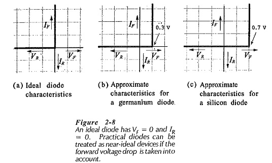
Diode Approximations – As we know already that, a diode is essentially a one-way device, offering a low resistance when forward biased, and a high resistance when biased in reverse. An ideal diode (or perfect diode) would have zero forward resistance and zero forward voltage drop. It would also have an infinitely high reverse resistance, which would result in zero reverse current. Figure 2-8(a) shows the current/voltage characteristics of an ideal diode.
Although an ideal diode does not exist, there are many applications where diodes can be assumed to be near-ideal devices.
In circuits with supply voltages much larger than the diode forward voltage drop, VF can be assumed constant without introducing any serious error. Also, the diode reverse current is normally so much smaller than the forward current that the reverse current can be ignored. These assumptions lead to the near-ideal, or approximate, characteristics for silicon and germanium diodes shown in Fig. 2-8(b) and (c).
Piecewise Linear Characteristic:
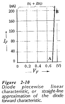
When the forward characteristic of a diode is not available, a straight-line Diode Approximations, called the piecewise linear characteristic, may be employed. To construct the piecewise linear characteristic, VF is first marked on the horizontal axis as shown in Fig. 2-10. Then, starting at VF, a straight line is drawn with a slope equal to the diode dynamic resistance.
DC Equivalent Circuits:
An equivalent circuit for a device is a circuit that represents the device behaviour. Usually, the equivalent circuit is made up of a number of components, such as resistors and voltage cells. A diode equivalent circuit may be substituted in place of the device when investigating a circuit containing the diode. Equivalent circuits may also be used as device models in computer analysis of circuits.
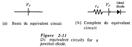
The forward-biased diode is assumed to have a constant forward voltage drop (VF) and negligible series resistance. In this case the dc equivalent circuit is assumed to be a voltage cell with a voltage VF , [see Fig. 2-11(a)]. This simple dc equivalent circuit is quite suitable for a great many diode applications.
A more accurate equivalent circuit includes the diode dynamic resistance (rd) in series with the voltage cell, as shown in Fig. 2-11(b). This takes account of the small variations in VF that occur with change in forward current. An ideal diode is also included to show that current flows only in one direction. The equivalent circuit without rd assumes that the diode has the approximate characteristics illustrated in Fig. 2-8(b) or (c). With rd included, the equivalent circuit represents a diode with the type of piecewise linear characteristic in Fig. 2-10. Consequently, the circuit in Fig. 2-11(b) is known as the piecewise linear equivalent circuit.


