Diode Failure Modes and Causes:
We would certainly like for solid-state components to be 100% reliable but this is unfortunately not true. All solid-state devices have a certain probability of failure. To be good circuit designers and/or good circuit troubleshooters, we should have some idea of the most likely failure modes for solid-state devices. This knowledge can help us anticipate Diode Failure in new circuit designs, and locate failures in a malfunctioning electronic circuit.
A diode or P-N junction may get open circuited or short circuited. The probability of the diodes becoming open circuited when they fail is not as great. In normal service usually, diode is short circuited.
Diode Failure generally happens when current flowing through the diode exceeds its rated value. In such cases, the diode is said to be burnt. Any way, the diode becomes useless in both cases (open circuited or short circuited).
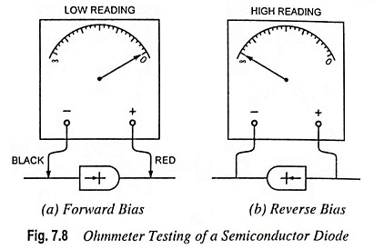
The best instrument for testing a semiconductor diode is an ohmmeter such as is found on the standard multimeter (or VOM). The internal battery (usually 1.5 V) of the ohmmeter section will either forward or reverse bias the diode when connected to it.
If the positive (normally the red) lead is connected to the cathode and the negative (normally the black) lead to the anode, the diode is forward biased and the meter should indicate a low value of resistance. With the reverse polarity, the diode will be reverse biased and the meter should indicate very large value of resistance. A large forward-bias resistance means an open circuit, while small reverse-bias resistance means a short-circuit condition. The basic connections for the tests are shown in Fig. 7.8.
Precautions To Be Taken During Testing of Diodes:
- An ohmmeter scale that has a high internal current should not be used because high current will damage the diode under test.
- One side of the diode should be disconnected from the circuit to eliminate any parallel resistance path. Tunnel diodes should not be checked with an ohmmeter.
