Driving Point Immittance Function:
The immitance function must be positive real function so that its synthesis can be done to obtain an electrical network, using passive elements. We have discussed the tests to confirm the positive realness of a given function. Let us study now how to synthesize the given Driving Point Immittance Function (impedance or admittance) which is positive real.
There are three types of passive elements which are an inductor (L), a capaciter (C) and a resistor (R). A given function can be synthesized using any two types of passive elements. Thus synthesized network can be LC network, RC network or RL network.
A network using any two types of passive elements can be synthesized generally in two forms called,
- Foster form and
- Cauer form.
These forms are used for the network realization because the network is realized using minimum number of passive elements using these basic forms. Hence these forms are called canonical or simple forms of realization. In each of these forms there are two subforms. The foster form is subdivided as Foster I form and Foster II forms while the Cauer form is subdivided as Cauer I and Cauer II forms.
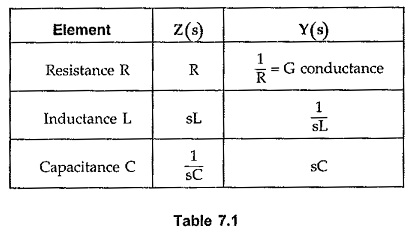
The following table is useful while realizing the network by any of the four forms mentioned above
Foster I Form:
The Foster I form uses the partial fractions of the driving point impedance function Z(s). The partial fraction expansion gives the equation of Z(s) as summation of the various impedance functions.
Thus a network can be realized by connecting the impedances Z1,Z2, ……..Zn in series.
Each impedance individually can be a series combination or parallel combination of the elements, which is to be identified. The identification of various elements existing in the different impedance function can be done by referring the Table 7.1. While finding the partial fractions, make sure that the degree of numerator is less than the degree of denominator. In this form, number of times, we get the functions after partial fraction expansion as,![]()
This can be synthesized by expressing it as
We know
The addition of two admittances indicate that there are two branches in parallel.
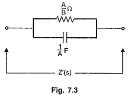
Referring to the Table 7.1, Y1(s) = s/A represents a capacitor of 1/A F while Y2(s) = B/A represents conductance of B/A mho i.e. a resistance of A/B ohms. Hence Z'(s) can be realized as parallel combination of R and C as shown in the Fig. 7.3.
Note that this example illustrates how to synthesize a particular function obtained in the partial fraction form. It does not mean that every time Foster I form gives RC networks.
Foster II Form:
The Foster II form uses the partial fractions of the driving point admittance function Y(s) = 1/Z(s). The partial fraction expansion gives the equation of Y(s) as summation of the various admittance functions.
Thus a network can be realized by connecting the admittances Y1, Y2, …… Yn in parallel.
Each admittance individually can be a series combination or parallel combination of the various elements. These combinations are to identified to realize the network. This can be easily done by referring the Table 7.1, as illustrated above.
Cauer I Form:
Basically Cauer form uses continued fraction expansion of the Driving Point Immittance Function. The Cauer I uses the continued fraction expansion of the driving point impedance function Z(s). In this form, the numerator and the denominator are arranged in the descending powers of s, starting from highest to lowest power of s.
This form gives the ladder structure of the network with alternate series and shunt arms. Hence this form of realization is also called ladder realization.
The continued fraction expansion gives the form as,
The continued fraction expansion can be obtained by the division and inversion procedure, used earlier for testing the Hurwitz polynomials.
In the continued fraction form of Z(s), the quotient of first division gives an impedance which is a series arm and then the quotients give alternately Y(s) and Z(s) terms representing shunt and series arms respectively.
The elements of each Z(s) and Y(s) obtained can be identified using the Table 7.1.
Remember that if the degree of numerator is same or less than the denominator, there is possibility of getting negative coefficients in the continued fraction expansion. In such case restart with the inversion and first quotient in such case represents admittance Y(s) which is a shunt arm. The series arm is absent in such case.
The Cauer I form is low pass structure of the network.
If the driving point admittance function Y(s) is expressed in continued fraction expansion with division at start, first quotient represents admittance Y(s) in shunt arm and then, alternately impedances and admittances in series and shunt arms respectively. Starting with inversion in such case gives impedance Z(s) in series arm as the first quotient, and then alternately admittances and impedances in shunt and series arms.
Cauer-II Form:
The Cauer II form also uses continued fraction expansion of the driving point immittance function either Z(s) or Y(s). In this form, the numerator and the denominator are arranged in the ascending powers of s, starting from lowest to highest power of s.
The continued fraction expansion gives the similar form as,
In this form also, there is a possibility of getting negative coefficients in the expansion procedure. In such a case, restart with the inversion, which gives Y(s) as the first quotient which indicates shunt arm, without a series arm in the circuit. Similarly driving point admittance function Y(s) also can be synthesized using Cauer II form.
The Cauer II form is basically high pass structure.
Remember that if Y(s) is to be synthesized and expansion starts with the division, first quotient gives Y(s) in shunt arm and if starts with the inversion, first quotient gives Z(s) in series arm and vice versa for Z(s).


