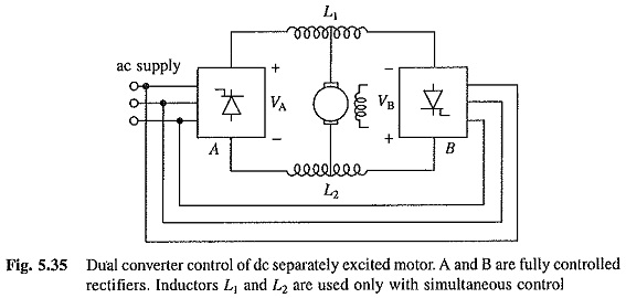
Dual Converter Control of DC Separately Excited Motor:
A Dual Converter Control of DC Separately Excited Motor (Fig. 5.35) consists of two fully-controlled rectifiers connected in anti-parallel across the armature. For power ratings upto around 10 kW, sigle-phase fully-controlled rectifiers can be used. For higher ratings, three-phase fully controlled rectifiers are employed. Rectifier A, which provides positive motor current and voltage in either direction, allows motor control in quadrants I and IV, Rectifier B provides motor control in quadrants III and II, because it gives negative motor current and voltage in either direction.
There are two methods of control for the Dual Converter Control of DC Separately Excited Motor:
(a) In simultaneous control both the rectifiers are controlled together. In order to avoid dc circulating current between rectifiers, they are operated to produce same de voltage across the motor terminals. Thus
Substituting from Eq. (5.97), yields
Although, control of firing angle according to relation (5.101) prevents dc circulating current, ac current does circulate due to difference between instantaneous output voltages of the two rectifiers. Inductors L1 and L2 are added to reduce ac circulating current. Because of the flow of ac circulating current, simultaneous control is also known as circulating current control. In a three-phase dual converter, inductors are chosen to allow a circulating current of 30% of full load current. This completely eliminates discontinuous conduction, and therefore, gives good speed regulation in the complete range of the drive.
The speed reversal is done as follows:
When operating in quadrant I, rectifier A will be rectifying (0 < αA < 90°) and rectifier B will be inverting (90° < αB < 180°). For speed reversal αA is increased and αB is decreased to satisfy eqn. 5.101. The motor back emf exceeds magnitudes of VA and VB. The armature current shifts to rectifier B and the motor operate in quadrant II. The current control loop adjusts the firing angle αB continuously so as to brake the motor at the maximum allowable current from initial speed to zero speed and then accelerates to the desired speed in the reverse direction. As αB is changed, αA is also changed to satisfy eqn. (5.101). The inductances L1 and L2 increase the weight, volume, cost and reversal time. The circulating current increases the losses. Sudden drop in source voltage can cause large current to flow through the rectifier working as inverter, blowing its thyristors.
(b) In non-simultaneous or non-circulating current control method, one rectifier is controlled at a time. Consequently, no circulating current flows and inductors L1 and L2 are not required. This eliminates losses associated with circulating current and weight and volume associated with inductors. But then discontinuous conduction occurs at light loads and control is rather complex.
The speed reversal is carried out as follows:
When operating in quadrant I rectifier A will be supplying the motor and rectifier B will not be operating. The firing angle of rectifier A is set at the highest value. The rectifier works as an inverter and forces the armature current to zero. After zero current is sensed, a dead time of 2 to 10 ms is provided to ensure the turn-off of all thyristors of rectifier A. Now firing pulses are withdrawn from rectifier A and transferred to rectifier B. The firing angle αB is set initially at the highest value. Now onwards the current control loop adjust the firing angle αB continuously so as to brake the motor at the maximum allowable current from initial speed to zero speed and then accelerates to the desired speed in the reverse direction. The dead time, and therefore, the reversal time can be reduced by employing methods which can sense the current zero accurately. When this is done non-simultaneous control provides faster response than simultaneous control. Because of this and the advantages stated above non-simultaneous control is widely used.

