Load Frequency Control of Isolated Power System:
To obtain the dynamic response of Load Frequency Control of Isolated Power System giving the change in frequency as function of the time for a step change in load, we must obtain the Laplace inverse of Eq. (8.14). The characteristic equation being of third order, dynamic response can only be obtained for a specific numerical case. However, the characteristic equation can be approximated as first order by examining the relative magnitudes of the time constants involved. Typical values of the time constants of Load Frequency Control of Isolated Power System are related as
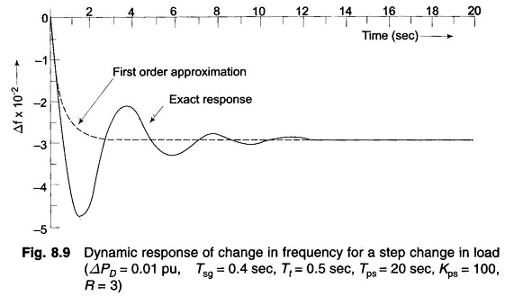
Typically Tsg = 0.4 sec, Tt = 0.5 sec and Tps = 20 sec.
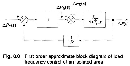
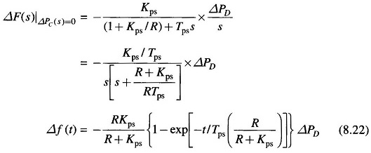
Letting Tsg = Tt = 0, (and Ksg Kt ≡ 1), the block diagram of Fig. 8.8, from which we can write
Taking R = 3, Kps = 1/B = 100, Tps = 20, ΔPD = 0.01pu
The plot of change in frequency versus time for first order approximation given above and the exact response are shown in Fig. 8.9. First order approximation is obviously a poor approximation.
Control Area Concept:
So far we have considered the simplified case of a single turbo-generator supplying an Load Frequency Control of Isolated Power System. Consider now a practical system with a number of generating stations and loads.
It is possible to divide an extended power system (say, national grid) into subareas (may be, State Electricity Boards) in which the generators are tightly coupled together so as to form a coherent group, i.e. all the generators respond in unison to changes in load or speed changer settings. Such a coherent area is called a control area in which the frequency is assumed to be the same throughout in static as well as dynamic conditions.
For purposes of developing a suitable control strategy, a control area can be reduced to a single speed governor, turbo-generator and load system. All the control strategies discussed so far are, therefore, applicable to an independent control area.


