Dynamics of Synchronous Machine:
The Kinetic Energy of the Rotor at Dynamics of a Synchronous Machine is
where
- J = rotor moment of inertia in Kg-m2
- ωsm = synchronous speed in rad (mech)/s
But
where
- P = number of machine poles
where
- M = J (2/P)2 ωs x 10-6
- = moment of inertia in MJ-s/elect rad
We shall define the inertia constant H such that
where
- G = machine rating (base) in MVA (3-phase)
- H = inertia constant in MJ/MVA or MW-s/MVA
It immediately follows that
M is also called the inertia constant.
Taking G as base, the inertia constant in pu is
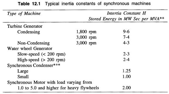
The inertia constant H has a characteristic value or a range of values for each class of machines. Table 12.1 lists some typical inertia constants.
It is observed from Table 12.1 that the value of H is considerably higher for steam turbogenerator than for water wheel generator. Thirty to sixty per cent of the total inertia of a steam turbogenerator unit is that of the prime mover, whereas only 4 – 15% of the inertia of a hydroelectric generating unit is that of the waterwheel, including water.
The Swing Equation:
Figure 12.1 shows the torque, speed and flow of mechanical and electrical powers in a synchronous machine. It is assumed that the windage, friction and iron-loss torque is negligible. The differential equation governing the rotor Dynamics of Synchronous Machine can then be written as
where
- θm = angle in rad (mech)
- Tm = turbine torque in Nm; it acquires a negative value for a motoring machine
- Te = electromagnetic torque developed in Nm; it acquires negative value for a motoring machine
While the rotor undergoes Dynamics of Synchronous Machine as per Eq. (12.3), the rotor speed changes by insignificant magnitude for the time period of interest (1s). Equation (12.3) can therefore be converted into its more convenient power form by assuming the rotor speed to remain constant at the synchronous speed (ωsm). Multiplying both sides of Eq. (12.3) by ωsm′ we can write
where
- Pm = mechanical power input in MW
- Pe = electrical power output in MW; stator copper loss is assumed negligible.
Rewriting Eq. (12.4)
where
- θe = angle in rad (elect)
It is more convenient to measure the angular position of the rotor with respect to a synchronously rotating frame of reference. Let
From Eq. (12.6)
Hence Eq. (12.5) can be written in terms of δ as
With M as defined in Eq. (12.1), we can write
Dividing throughout by G, the MVA rating of the machine,
where
This equation (Eq. (12.10)/Eq. (12.11)), is called the swing equation and it describes the rotor dynamics for a synchronous machine (generating/motoring). It is .a second-order differential equation where the damping term (proportional to dδ/dt) is absent because of the assumption of a lossless machine and the fact that the torque of damper winding has been ignored. This assumption leads to pessimistic results in transient stability analysis—damping helps to stabilize the system. Damping must of course be considered in a dynamic stability study. Since the electrical power Pe depends upon the sine of angle δ, the swing equation is a non-linear second-order differential equation.
Multimachine System:
In a multimachine system a common system base must be chosen.
Let
Equation (12.11) can then be written as
where
Machines Swinging Coherently:
Consider the swing equations of two machines on a common system base.
Since the machine rotors swing together (coherently or in unison)
Adding Eqs (12.14) and (12.15)
where
The two machines swinging coherently are thus reduced to a single machine as in Eq. (12.16). The equivalent inertia in Eq. (12.17) can be written as
The above results are easily extendable to any number of machines swinging coherently.


