Earth Fault Protection or Leakage Protection:
An Earth Fault Protection usually involves a partial breakdown of winding insulation to earth. The resulting leakage current is considerably less than the short-circuit current, The Earth Fault Protection may continue for a long time and cause considerable damage before it ultimately develops into a short-circuit and removed from the system. Under these circumstances, it is profitable to employ earth-fault relays in order to ensure the disconnection of Earth Fault Protection or Leakage Protection in the early stage.
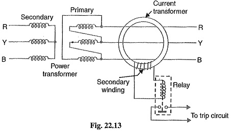
An earth-fault relay is essentially an overcurrent relay of low setting and operates as soon as an earth-fault or leak develops. One method of protection against earth-faults in a transformer is the core-balance leakage protection shown in Fig. 22.13.
The three leads of the primary winding of power transformer are taken through the core of a current transformer which carries a single secondary winding. The operating coil of a relay is connected to this secondary. Under normal conditions (i.e. no fault to earth), the vector sum of the three phase currents is zero and there is no resultant flux in the core of current transformer no matter how much the load is out of balance.
Consequently, no current flows through the relay and it remains inoperative. However, on the occurrence of an, earth-fault, the vector sum of three phase currents is no longer zero. The resultant current sets up flux in the core of the C.T. which induces e. m. f. in the secondary winding. This energizes the relay to trip the circuit breaker and disconnect the faulty transformer from the system.
Combined Leakage and Overload Protection:
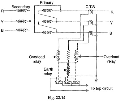
The core-balance protection described above suffers from the drawback that it cannot provide protection against overloads. If a fault or leakage occurs between phases, the core-balance relay will not operate. It is a usual practice to provide combined leakage and overload protection for transformers. The earth relay has low current setting and operates under earth or leakage faults only. The overload relays have high current setting and are arranged to operate against faults between the phases.
Fig. 22.14 shows the schematic arrangement of combined leakage and overload protection. In this system of protection, two overload relays and one leakage or earth relay are connected as shown. The two overload relays are sufficient to protect against phase-to-phase faults. The trip contacts of overload relays and earth-fault relay are connected in parallel. Therefore, with the energizing of either overload relay or earth relay, the circuit breaker will be tripped.

