Effect of Earth on Capacitance of Transmission Line:
In calculating the Effect of Earth on Capacitance of Transmission Line, the presence of earth was ignored, so far. The effect of earth on Capacitance of Transmission Line can be conveniently taken into account by the method of images.
Method of Images:
The electric field of transmission line conductors must conform to the presence of the earth below. The earth for this purpose may be assumed to be a perfectly conducting horizontal sheet of infinite extent which therefore acts like an equipotential surface.
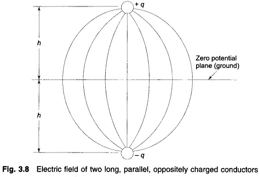
The electric field of two long, parallel conductors charged +q and -q per unit is such that it has a zero potential plane midway between the conductors as shown in Fig. 3.8. If a conducting sheet of infinite dimensions is placed at the zero potential plane, the electric field remains undisturbed. Further, if the conductor carrying charge -q is now removed, the electric field above the conducting sheet stays intact, while that below it vanishes. Using these well known results in reverse, we may equivalently replace the presence of ground below a charged conductor by a fictitious conductor having equal and opposite charge and located as far below the surface of ground as the overhead conductor above it—such a fictitious conductor is the mirror image of the overhead conductor. This method of creating the same electric field as in the presence of earth is known as the method of images originally suggested by Lord Kelvin.
Capacitance of a Single-Phase Line:
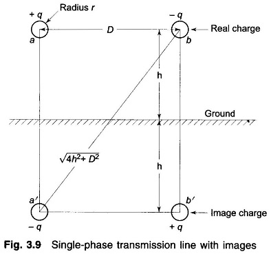
Consider a single-phase line shown in Fig. 3.9. It is required to calculate its Capacitance of Transmission Line taking the presence of earth into account by the method of images described above. The equation for the voltage drop Vab as determined by the two charged conductors a and b, and their images a’ and b’ can be written as follows:
Substituting the values of different charges and simplifying, we get
It immediately follows that
and
It is observed from the above equation that the presence of earth modifies the radius r to r(1 + (D2/4h2))1/2. For h large compared to D (this is the case normally), the effect of earth on line capacitance is of negligible order.
Capacitance of a Three-Phase Line:
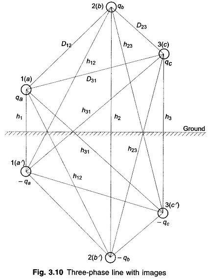
The method of images can similarly be applied for the calculation of Capacitance of Transmission Line of a three-phase line, shown in Fig. 3.10. The line is considered to be fully transposed. The conductors a, b and c carry the charges qa, qb and qc and occupy positions 1, 2, and 3, respectively, in the first section of the transposition cycle. The effect of earth is simulated by image conductors with charges -qa, -qb and -qc respectively, as shown.
The equations for the three sections of the transposition cycle can be written for the voltage drop Vab as determined by the three charged conductors and their images. With conductor a in position 1, b in position 2, and c in position 3,
Similar equations for Vab can be written for the second and third sections of the transposition cycle. If the fairly accurate assumption of constant charge per unit length of the conductor throughout the transmission cycle is made, the average value of Vab for the three sections of the cycle is given by
where Deq = (D12D23D31)1/3
The equation for the average value of the phasor Vac is found in a similar manner. Proceeding on the lines and using Vab + Vac = 3Van and qa + qb + qc = 0, we ultimately obtained the following expression for the capacitance to neutral.
or
Comparing Eqs. (3.22a) and (3.29a), it is evident that the effect of earth is to increase the capacitance of a line. If the conductors are high above earth compared to the distances among them, the effect of earth on the capacitance of three-phase lines can be neglected.


