Effects of Antenna Height:
At low and medium frequencies, where wavelengths are long, it often becomes impracticable to use an antenna of resonant length. The vertical antennas used at those frequencies are too short electrically. The Effects of Antenna Height are
Top loading:
The actual antenna height should be at least a quarter-wavelength, but where this is not possible, the effective height should correspond to λ/4. An antenna much shorter than this is not an efficient radiator and has a poor input impedance with a low resistance and a large capacitive reactance component. The input impedance at the base of a λ/8 Marconi antenna is only about (8 – j500) Ω. With this low value of radiation resistance, antenna efficiency is low. Because of the large capacitive component, matching to the feeder transmission line is difficult. This second problem can be partly overcome by an inductance placed in series with the antenna. This does not increase the resistive component of the impedance but does effectively lengthen the Effects of Antenna Height.
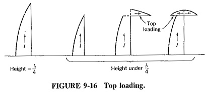
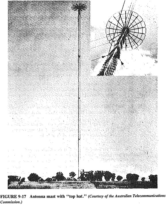
A good method of increasing radiation resistance is to have a horizontal portion at the top of the antenna. The effect of such top loading, as shown in Figure 9-16, is to increase the current at the base of the antenna, and also to make the current distribution more uniform. Top loading may take the form of a single horizontal piece, resulting in the inverted-L and T antennas of Figure 9-16. It may also take the form of a “top hat,” as shown in Figure 9-17. The top hat also has the effect of adding capacitance in series with the antenna, thus reducing its total capacitive input reactance.
The radiation pattern of a top-loaded antenna is similar to that of the basic Marconi, because the current distribution is almost the same, as shown in Figure 9-16. Since the current in the horizontal portion is much smaller than in the vertical part, the antenna is still considered to be vertically polarized. More often than not, the decision as to what type of top load to use and how much of it to have is dictated by the facilities available and costs, rather than by optimum design factors. We might add that design in this case is often inspired guesswork, especially in the case of top-loaded tapering towers.
Optimum length:
When considering MF (medium-frequency) antennas, we should note that there are times when an antenna is too tall. An antenna whose height is a wavelength is useless for ground-wave propagation, because it radiates nothing along the ground. An optimum height must exist somewhere between “too short” and a full wavelength. A we know that the horizontal field strength increases with height, up to about 5/8 λ. Unfortunately, when the Effects of Antenna Height exceeds λ/2, other lobes are formed. Depending on their strength and angle, their interaction will cause objectionable sky-wave interference. This holds true for all vertical radiators taller than about 0.53 λ, so that this height is not exceeded in practice for antennas used in ground-wave propagation.
Effective length:
The term effective electrical length has been used on a number of occasions. It refers to the fact that antennas behave as though (electrically) they were taller than their physical height. The first reason for this is the effect of top loading. The second reason is generally called End effects, the result of physical antennas having finite thickness, instead of being infinitely thin. In consequence, the propagation velocity within the antenna is some 2 to 8 percent less than in free space, so that the wavelength within the antenna is shorter by the same amount. The antenna thus appears longer than if wavelength had been calculated on the basis of velocity in free space. Finally, if the cross section of the Effects of Antenna Height is nonuniform, as in tapered towers, this last situation is further complicated.
For all the preceding reasons, it is standard procedure to build these antennas slightly taller than needed and then to trim them down to size. This procedure is generally more effective than length calculation or from charts available in antenna handbooks and can be accomplished by using an SWR meter and a trimming tool.

