Effects of Ground on Antenna Performance:
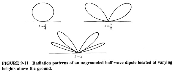
The Effects of Ground on Antenna Performance on a detailed discussion of the interaction (see Figure 9-11).
Ungrounded Antennas:
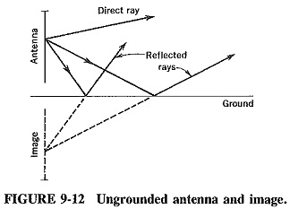
As was know, when a radiation source is placed near a reflecting surface, the signal received at any distant point is the vector sum of the direct (sometimes called the incident) wave and the reflected wave. To simplify the explanation, an image antenna is visualized to exist below the earth’s surface and is a true mirror image of the actual antenna (Figure 9-12).
When a wave is reflected, its polarity is changed by 180°. If direct and reflected waves of equal magnitude and phase angle are received at exactly the same time, the two signals will cancel each other out (the vector sum is equal to zero). This condition is rarely achieved in reality, but combinations of this effect can cause reception to fade (if the signals are out of phase) or increase (if the reflections happen to be in phase, i.e., voltage vector addition).
Grounded Antennas:
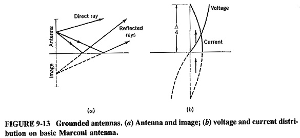
If an antenna is grounded, the earth still acts as a minor and becomes part of the radiating system. The ungrounded antenna with its image forms a dipole array, but the bottom of the grounded antenna is joined to the top of the image. The system acts as an antenna of double size. Thus, as shown in Figure 9-13a, a grounded quarter-wave vertical radiator effectively has a quarter-wavelength added to it by its image. The voltage and current distributions on such a grounded λ/4 antenna (commonly called the Marconi antenna), are the same as those of the half-wave dipole in space and are shown in Figure 9-13b.
The Marconi antenna has one important advantage over the ungrounded, or Hertz, antenna: to produce any given radiation pattern, it need be only half as high. On the other hand, since the ground here plays such an important role in producing the required radiation patterns, the ground conductivity must be good. Where it is poor, an artificial ground is used.
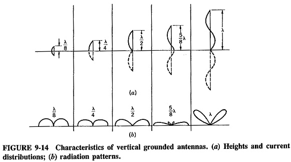
The radiation pattern of a Marconi antenna depends on its height, and a selection of patterns is shown in Figure 9-14. It is seen that horizontal directivity improves with height up to a certain point (5/8 λ), after which the pattern “lifts off ” the ground.
The effect is caused by cancellation of the wave in the horizontal direction because of opposing currents in the various parts of an Effects of Ground on Antenna Performance at this effective height.
Grounding Systems:
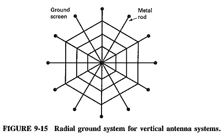
The earth has generally been assumed to be a perfect conductor so far. This is often not the case. For this reason the best ground system for a vertical grounded radiator is a network of buried wires directly under the Effects of Ground on Antenna Performance. This network consists of a large number of “radials” extending from the base of the tower, like spokes on a wheel, and placed between 15 and 30 cm below the ground. Each radial wire has a length which should be at least λ/4, and preferably λ/2. Up to 120 such wires may be used to good advantage, and the whole assembly is then known as a ground screen.
A conductor joining all the radials, at a distance of about half the radial length, is often employed. The far end of each radial is grounded, i.e., attached to a metal stake which is driven deeply into the subsoil (especially if this is a better conductor than the topsoil, as in sandy locations).
A good ground screen will greatly improve the field strength and distance of Marconi antennas, especially those used for medium-frequency broadcasting. The improvement is most pronounced for short antennas (under λ/4 in height) and/or with soils of poor conductivity. Even an antenna between λ/4 and λ/2, on soil with good conductivity, will have its radiation pattern improved noticeably.
Where a ground screen is not practical, a counterpoise is used. A counterpoise consists of a system of radials, supported above ground and insulated from it. The supports should be few and far between and made of a material such as metal rods, with low dielectric losses. The counterpoise would be a substitute for a ground screen in areas of low ground conductivity, i.e., rock, mountains, and antennas on top of buildings (Figure 9-15).
