Electric Generator Diagram:
Electric Generator Diagram – Electricity does not occur naturally in usable form and it also cannot be stored in usefully large quantities. Therefore, it must be generated continuously to meet the demand (of power) at all times. An efficient and convenient way to generate electric power is by conversion of mechanical power into electrical form in a Rotating device called a generator. In the process a small part of power is lost in the generator (efficiencies in large generators are above 90%).
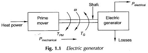
The mechanical power is itself obtained from heat power by thermodynamical means in a steam turbine (efficiency in the range of 40-50% as the present upper limit) or by conversion of Potential Energy of water in a hydraulic turbine with very little loss. The basic source of mechanical power steam/hydraulic turbine is called the Prime Mover. Electricity can also be generated directly from hot gases in Plasma form, obviating the need of converging heat power to intermediate mechanical power. This process is still in an experimental stage. The Electromechanical process of Electric Generator Diagram is shown schematically in Fig. 1.1. Under steady conversion conditions,
TPM (prime mover) = TG (generator) and the turbine and generator run at steady speed.
Other than lighting and heating, the major use of electric energy is made by converting it back to the mechanical form to run the wheels of industry as well as tiny household appliances. The intermediary, the electric power, permits the use of large efficient central generating stations, while it is easily transported to the myriads of use points.
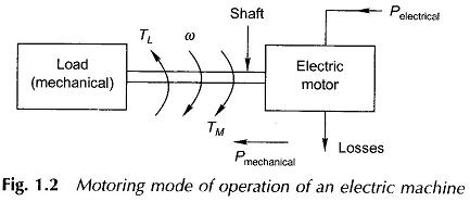
The electromechanical energy conversion process is a reversible one and simple adjustment of mechanical shaft and electrical conditions reverses the flow of power as illustrated in Fig. 1.2.
In this mode of operation, the electromechanical device, in general called the Electrical Machines, is known as the motor and the machine is said to be in the motoring mode. Under steady speed operation, again TM (motor) = TL (load). Both in generating and motoring modes, losses occur in the Electrical Machines but the overall conversion efficiencies are very high (close to or above 90%).
Electric Generator Working are employed in almost every industrial and manufacturing process. Pages can be filled in listing the applications of Electrical Machines right from giant-size generators (500 MW and above), industrial motors ranging up to a few megawatts to fractional-kW domestic appliances and to sophisticated aerospace applications requiring stringent reliability in operation.
Electric Generator Diagram Working deals with the important topic of Electrical Machines, the in-depth understanding of which is necessary to tackle the problems of energy, pollution and poverty that presently confront the whole of mankind.
Since Thomas Alva Edison developed an electric. generator, more than hundred years ago, engineers have continually strived and successfully reduced the size and revised upwards the efficiencies of Electrical Machines by the use of improved materials and optimal design strategies. We appear to have reached close to the upper limit imposed by nature.
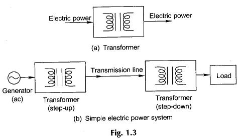
A transformer is a static device that transforms electric energy from one ac voltage level to another. It is this device that has made the electric system almost universally ac. The electric power is generated at relatively low voltages (up to a maximum of 33 kV) which then is raised to very high voltages (e.g. 756 kV) by means of a transformer and then transmitted. High voltages are associated with low currents and reduced transmission losses. Geographically close to the use points, the electric power is transformed back to safe low utility voltages (400/231 V). A transformer consists basically of two coils (three sets of coil pairs for a 3-phase system) tightly coupled by means of magnetic (steel) core.
Figure 1.3(a) gives the symbolic representation of a transformer and Fig. 1.3(b) shows a simple electric power generation transmission and reception system. A practical electric power system is an integrated one, far more complex than the simple diagrammatic representation of Fig. 1.3(b), and is in the form of an interconnected network for reasons of economy, operational efficiency and reliability. Because the principle of rotating ac machines is akin to that of a transformer, these two are always studied together in a book. Further, since the transformer analogy can be extended to both the ac machine types, the transformer study usually precedes the machine study.

