AC Analysis of FET Circuits Articles:
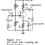
Coupling Capacitors: Coupling Capacitors are required at a circuit input to couple a signal source to the circuit without affecting the bias conditions. Similarly, loads are capacitor-coupled to the circuit output to avoid the change in bias conditions produced by direct … (Read More)
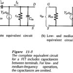
FET Equivalent Circuit Model: The complete FET Equivalent Circuit Model is shown in Fig. 11-5(a). It is seen that tilt source terminal is common to both input and out, so this is a common-source equivalent circuit. Resistor RGS between the gate … (Read More)
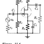
Common Source Circuit Analysis: A FET Common Source Circuit Analysis is shown in Fig. 11-6. With the capacitors treated as ac short-circuits, the circuit input terminals are the gate and source, and the output terminals are the drain and the source. … (Read More)
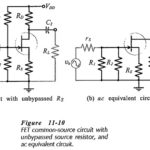
FET Common Source Amplifier with Unbypassed Source Resistors: Equivalent Circuit – When an unbypassed source resistor (RS) is present in a FET Common Source Amplifier circuit, as shown in Fig.11-10(a), it also appears in the ac equivalent circuit, . In the … (Read More)
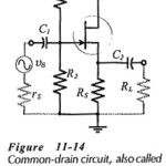
Common Drain Amplifier Circuit Diagram: The FET Common Drain Amplifier Circuit Diagram shown in Fig. 11-14 has the output voltage developed across the source resistor (RS). The external load (RL) is capacitor-coupled to the source terminal of the FET, and the … (Read More)
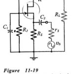
Common Gate Circuit: The FET Common Gate Circuit (CG) shown in Fig. 11-19 uses voltage divider bias. The ac output is taken from the drain terminal, and an external load (RL) is capacitor-coupled to the drain, exactly as in the case … (Read More)
FET and BJT Difference: FET and BJT Difference (CS, CD, and CG Circuit Comparison) – Table 11-1 compares Zi, Zo and Av for CS, CD, and CG circuits. As already discussed, the CS circuit has voltage gain, high input impedance, high output impedance, … (Read More)
Frequency Response of FET Amplifier: Low-Frequency Response – The low Frequency Response of FET Amplifier circuits is determined by exactly the same considerations as for BJT circuits. The lower cutoff frequency is normally set by a source bypass capacitor, and it … (Read More)
