Electrodynamometer Instrument:
Electrodynamometer Instrument – The D’Arsonval movement responds to the average or dc value of the current flowing through the coil. If ac current is sought to be measured, the current would flow through the coil with positive and negative half cycles, and hence the driving torque would be positive in one direction and negative in the other. If the frequency of the ac is very low, the pointer would swing back and forth around the zero point on the meter scale.
At higher frequencies, the inertia of the coil is so great that the pointer does not follow the rapid variations of the driving torque and vibrates around the zero mark.
Therefore, to measure ac on a D’Arsonval movement, a rectifier has to be used to produce a unidirectional torque. This rectifier converts ac into dc and the rectified current deflects the coil. Another method is to use the heating effect of ac current to produce an indication of its magnitude. This is done using an electrodynamometer (EDM).
An electrodynamometer is often used in accurate voltmeter and ammeters not only at power line frequency but also at low AF range. The electrodynamometer can be used by slightly modifying the PMMC movement. It may also serve as a transfer instrument, because it can be calibrated on dc and then used directly on ac thereby equating ac and dc measurements of voltage and current directly.
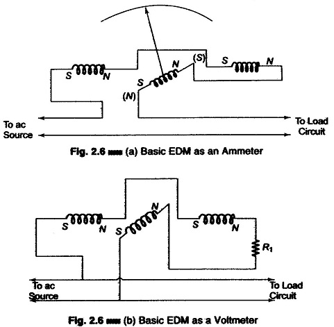
A movable coil is used to provide the magnetic field in an electrodynamometer, instead of a permanent magnet, as in the D’Arsonval movement. This movable coil rotates within the magnetic field. The EDM uses the current under measurement to produce the required field flux. A fixed coil, split into two equal halves provides the magnetic field in which the movable coil rotates, as shown in Fig. 2.6 (a). The coil halves are connected in series with the moving coil and are fed by the current being measured. The fixed coils are spaced far apart to allow passage for the shaft of the movable coil. The movable coil carries a pointer, which is balanced by counterweights. Its rotation is con¬trolled by springs, similar to those in a D’Arsonval movement.
The complete assembly is surrounded by a laminated shield to protect the instrument from stray magnetic field which may affect its operation.
Damping is provided by aluminium air vanes moving in a sector shaped chamber. (The entire movement is very solid and rigidly constructed in order to keep its mechanical dimensions stable, and calibration intact.)
The operation of the instrument may be understood from the expression for the torque developed by a coil suspended in a magnetic field, i.e.
indicating that the torque which deflects the movable coil is directly proportional to the coil constants (A and N), the strength of the magnetic field in which the coil moves (B), and the current (I) flowing through the coil.
In an EDM the flux density (B) depends on the current through the fixed coil and is therefore proportional to the deflection current (I). Since the coil constants are fixed quantities for any given meter, the developed torque becomes a function of the current squared (I2).
If the EDM is used for dc measurement, the square law can be noticed by the crowding of the scale markings at low current values, progressively spreading at higher current values.
For ac measurement, the developed torque at any instant is proportional to the instantaneous current squared (i2). The instantaneous values of i2 are always positive and torque pulsations are therefore produced.
The meter movement, however, cannot follow rapid variations of the torque and take up a position in which the average torque is balanced by the torque of the control springs. The meter deflection is therefore a function of the mean of the squared current. The scale of the EDM is usually calibrated in terms of the square root of the average current squared, and therefore reads the effective or rms value of the ac.
The transfer properties of the EDM become apparent when we compare the effective value of the alternating current and the direct current in terms of their heating effect, or transfer of power.
(If the EDM is calibrated with a direct current of 500 mA and a mark is placed on the scale to indicate this value, then that ac current which causes the pointer to deflect to the same mark on the scale must have an rms value of 500 mA.)
The EDM has the disadvantage of high power consumption, due to its construction. The current under measurement must not only pass through the movable coil, but also provide the necessary field flux to get a sufficiently strong magnetic field. Hence high mmf is required and the source must have a high current and power.
In spite of this high power consumption the magnetic field is still weaker than that of the D’Arsonval movement because there is no iron in the path, the entire flux path consisting of air.
The EDM can be used to measure ac or dc voltage or current, as shown in Figs. 2.6 (a) and (b).
Typical values of EDM flux density are in the range of approximately 60 gauss as compared to the high flux densities (1000 — 4000 guars) of a good D’Arsonval movement. The low flux density of the EDM affects the developed torque and therefore the sensitivity of the instrument.
The addition of a series multiplier converts the basic EDM into a voltmeter [Fig. 2.6 (b)] which can be used for ac and dc measurements. The sensitivity of the EDM voltmeter is low, approximately 10 – 30 Ω/V, compared to 20 kΩ/V of the D’Arsonval movement. It is however very accurate at power line frequency and can be considered as a secondary standard.
The basic EDM shown in Fig. 2.6 (a) can be converted into an ammeter (even without a shunt), because it is difficult to design a moving coil which can carry more than approximately 100 mA.
The EDM movement is extensively used to measure power, both dc and ac, for any waveform of voltage and current.
An EDM used as a voltmeter or ammeter has the fixed coils and movable coil connected in series, thereby reacting to I2.
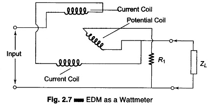
When an EDM is used as a single phase wattmeter, the coil arrangement is different, as shown in Fig. 2.7.
The fixed coils, shown in Fig. 2.7 as separate elements, are connected in series and carries the total line current. The movable coil located in the magnetic field of the fixed coils is connected in series with a current-limiting resistor across the power line, and carries a small current.
The deflection of the movable coil is proportional to the product of the instantaneous value of current in the movable coil and the total line current. The EDM wattmeter consumes some power for the maintenance of its magnetic field, but this is usually small compared to the load power.

