Electromagnetic Attraction Relay – Working Principle and its types:
Electromagnetic attraction relay operate by virtue of an armature being attracted to the poles of an electromagnet or a plunger being drawn into a solenoid. Such Basic Relays may be actuated by d.c. or a.c. quantities.
The important types of electromagnetic attraction relays are :
- Attracted armature type relay
- Solenoid type relay
- Balanced beam type relay
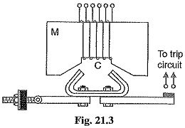
1. Attracted armature type relay: Fig. 21.3 shows the schematic arrangement of an attracted armature type relay. It consists of a laminated electromagnet M carrying a coil C and a pivoted laminated armature. The armature is balanced by a counterweight and carries a pair of spring contact fingers at its free end. Under normal operating conditions, the current through the relay coil C is such that counterweight holds the armature in the position shown. However, when a short cir suit occurs, the current through the relay coil increases sufficiently and the relay armature is attracted upwards. The contacts on the Basic Relays armature bridge a pair of stationary contacts attached to the relay frame. This completes the trip circuit which results in the opening of the circuit breaker and, therefore, in the disconnection of the faulty circuit.
The minimum current at which the relay armature is attracted to close the trip circuit is called pickup current. It is a usual practice to provide a number of tappings on the relay coil so that the number of turns in use and hence the setting value at which the relay operates can be varied.
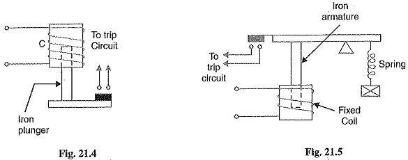
2. Solenoid type relay: Fig. 21.4 shows the schematic arrangement of a solenoid type Basic Relays. It consists of a solenoid and movable iron plunger arranged as shown. Under normal operating conditions, the current through the relay coil C is such that it holds the plunger by gravity or spring in the position shown. However, on the occurrence of a fault, the current through the relay coil becomes more than the pickup value, causing the plunger to be attracted to the solenoid. The upward movement of the plunger closes the trip circuit, thus opening the circuit breaker and disconnecting the faulty circuit.
3. Balanced beam type relay: Fig. 21.5 shows the schematic arrangement of a balanced beam type relay. It consists of an iron armature fastened to a balance beam. Under normal operating conditions, the current through the relay coil is such that the beam is held in the horizontal position by the spring. However, when a fault occurs, the current through the relay coil becomes greater than the pickup value and the beam is attracted to close the trip circuit. This causes the opening of the circuit breaker to isolate the faulty circuit.

