Electromechanical Breakdown and Thermal Breakdown:
Electromechanical Breakdown:When solid dielectrics are subjected to high electric fields, failure occurs due to electrostatic compressive forces which can exceed the mechanical compressive strength. If the thickness of the specimen is d0 and is compressed to a thickness d under an applied voltage V, then the electrically developed compressive stress is in equilibrium if
where Y is the Young’s modulus.
Usually, mechanical instability occurs when
Substituting this in Eq. 4.2, the highest apparent electric stress before breakdown,
The above equation is only approximate as Y depends on the mechanical stress. Also when the material is subjected to high stresses the theory of elasticity does not hold good, and plastic deformation has to be considered.
Recently, this theory has been modified based on the concept of fracture mechanics. In the new mechanism, filamentary shaped cracks propogate through the dielectric material releasing both the electrostatic energy and the Electromechanical Breakdown strain energy stored in the material due to the applied electric field. This is analogous to the conventional mechanical crack propogation in brittle materials, where by the cracks propogate spontaneously, if the strain energy released is greater than that required to overcome the toughness of the material.
Thermal Breakdown:
In general, the breakdown voltage of a solid dielectric should increase with its thickness. But this is true only up to a certain thickness above which the heat generated in the dielectric due to the flow of current determines the conduction. When an electric field is applied to a dielectric, conduction current, however small it may be, flows through the material. The current heats up the specimen and the temperature rises. The heat generated is transferred to the surrounding medium by conduction through the solid dielectric and by radiation from its outer surfaces. Equilibrium is reached when the heat used to raise the temperature of the dielectric, plus the heat radiated out, equals the heat generated. The heat generated under d.c. stress E is given as
where, σ is the d.c. conductivity of the specimen.
Under a.c. fields, the heat generated
where,
f= frequency in Hz,
δ = loss angle of the dielectric material, and
E = rms value.
The heat dissipated (WT) is given by
where
CV = specific heat of the specimen,
T = temperature of the specimen,
K = thermal conductivity of the specimen, and
t = time over which the heat is dissipated.
Equilibrium is reached when the heat generated (Wd.c. or Wa.c.) becomes equal to the heat dissipated (WT). In actual practice there is always some heat that is radiated out.
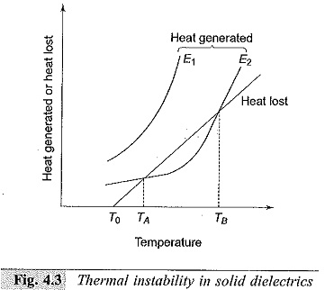
Breakdown occurs when Wd.c. or Wa.c. exceeds WT. The thermal instability condition is shown in Fig. 4.3. Here, the heat lost is shown by a straight line, while the heat generated at fields E1 and E2 are shown by separate curves. At field E2 breakdown occurs both at temperatures TA and TB. In the temperature region of TA and TB heat generated is less than the heat lost for the field E2, and hence the breakdown will not occur.
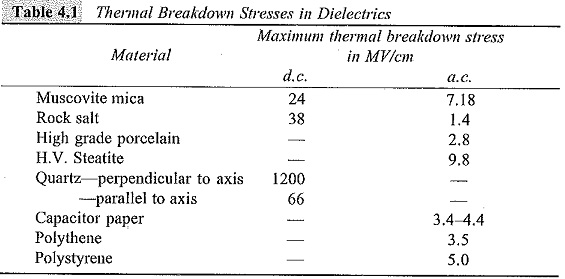
This is of great importance to practicing engineers, as most of the insulation failures in high voltage power apparatus occur due to thermal breakdown. Thermal breakdown sets up an upper limit for increasing the breakdown voltage when the thickness of the insulation is increased. For a given loss angle and applied stress, the heat generated is proportional to the frequency and hence thermal breakdown is more serious at high frequencies. Table 4.1 gives the thermal breakdown voltages of various materials under d.c. and a.c. fields.
It can be seen from this table that since the power loss under a.c. fields is higher, the heat generation is also high, and hence the thermal breakdown stresses are lower under a.c. conditions than under d.c. conditions.


