Electronic Relays:
Electronic Relays – These were the first to be developed in the series of static relays. They date back to early 1928 when Fitzgerald presented a carrier current pilot relaying which constituted unit protection of the transmission line.
Subsequently a series of electronic circuits for most of the common types of protective gear relays were developed. The components used were electronic valves for measuring unit.
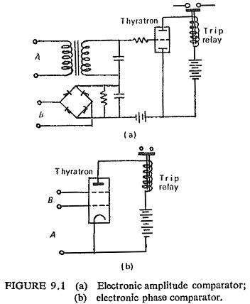
The two basic arrangements one as an amplitude comparator and another as a phase comparator are shown in Fig. (9.1). In the former case two a.c. quantities to be compared are rectified and applied in opposition in the control grid circuit of an electronic tube, so that operation occurs when one quantity exceeds the other by an amount depending on the bias.
In the latter case one a.c. quantity can be connected to the control grid of an electronic tube and the other a.c. quantity to the screen grid of the tube, operation occurs when the two quantities are in phase.
Electronic relays offer the following advantages:
- Low burden on CTs and PTs, since the operating power is from an auxiliary d.c. supply.
- Absence of mechanical inertia and bouncing contacts.
- Fast operation.
- Low maintenance, owing to the absence of moving parts.
In spite of all these however electronic relays have not met with general success except for carrier current relaying which has attained widespread use. The major reason is that carrier relaying has accomplished a highly desirable result not economically feasible by any other method.
This popularity is in spite of the following limitations of the electronic circuits.
- Presence of incandescent filament and necessary low-voltage power supply to heat them.
- Short life of the electronic valves.
- High power consumption.
- Requirement of high-tension supply.
- High cost for simple relays such as overcurrent relay.
