EMF and Torque Equation of DC Machine:
EMF and Torque Equation of DC Machine – It was shown in Sec. 5.2 (Fig. 5.14 (a)) that in a dc machine the magnetic structure is such that the flux density wave in the air-gap is flat-topped with quarter-wave symmetry so long as the armature is not carrying any current. It will be seen in Sec. 7.6 that the flux density wave gets distorted when the armature carries current (armature reaction effect destroys quarter-wave symmetry). However, this fact does not affect the constancy of emf (between brushes) and torque developed by the machine with magnitudes of each of these being determined by the flux/pole independent of the shape of the B-wave. We will see EMF and Torque Equation of DC Machine one by one.
EMF Equation of DC Machine:
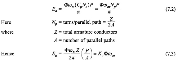
As per Eq. (5.23), the average coil emf is
where ωm = armature speed in rad/s,
Let
This number is fixed independent of the armature rotation; as one coil moves out of the parallel path another comes in and takes its place . Thus, the parallel path emf which equals the armature/ emf is given by
Ea remains constant (dc) by virtue of fixed coils per parallel path independent of rotation of armature (commutation action). It is also observed that Ea depends upon the flux/pole and not upon the shape of the flux density wave.
Torque Equation of DC Machine:
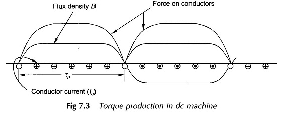
Figure 7.3 shows the flux density wave in the air-gap and the conductor current distribution in the developed armature for one pole-pair. It is immediately seen that
the force on conductors is unidirectional. Each conductor as it moves around with the armature experiences a force whose time variation is a replica of the B-wave. Therefore, the average conductor force
This force (and therefore torque) is constant (independent of time) because both the flux density wave and current distribution are fixed in space at all times. Now the torque developed
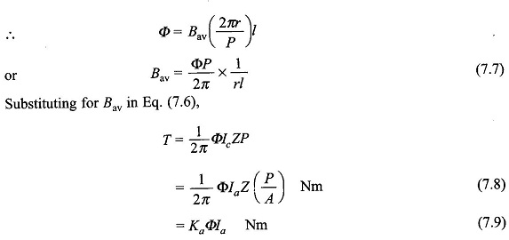
It is, therefore, seen that the machine torque is uniform for given flux/pole and armature current. Further, it is independent of the shape of the B-wave, which in fact gets distorted by the armature mmf when it carries current (see Sec. 7.5).
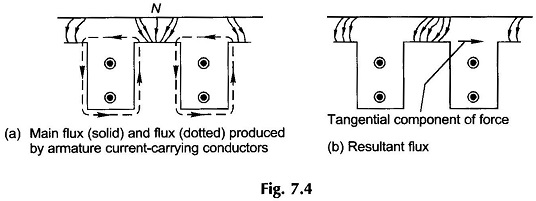
It is convenient to use force on each conductor in deriving the expression for armature torque. However, the mechanism of torque production is different in an actual machine in which conductors are placed in armature slots. The force is produced by the interaction of the main flux and the flux produced by current carrying conductors placed in armature slots. Due to the large reluctance of the air-path of slots, the main flux passing through the conductors is negligible and so is the force acting on the conductor. Force is produced mainly by the distortion of the flux lines passing through the teeth, and this force acts on the teeth of the armature as shown in Fig. 7.4. It is rather fortunate that there is very little force acting on conductors. If all the force were to act on conductors, it would crush the insulation between conductors and slots.
Power Balance:
Mechanical power
This is nothing but a statement of energy conservation, i.e. electrical and mechanical powers must balance in a machine.
From Eq. (7.10),
Linear Magnetization:
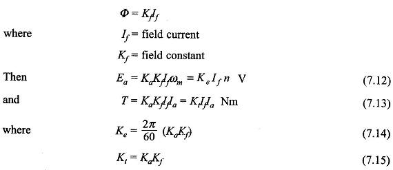
If the magnetic circuit of the machine is assumed linear
The derivation of torque developed (Eq. (7.8)) using magnetic field interaction is carried out in Sec. 7.5 after armature reaction ampere turns are determined
