Feedback Amplifiers Articles:
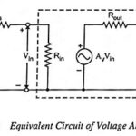
Voltage Amplifier – Definition and Equivalent Circuit: Voltage amplifiers are intended to amplify an input voltage signal and provide an output voltage signal. The voltage amplifiers is essentially a voltage-controlled voltage source. The input impedance is required to be high and … (Read More)
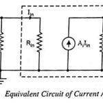
Current Amplifier – Definition and Equivalent Circuit: The input signal in a current amplifier is essentially a current, and thus the signal source is most conveniently represented by its Norton equivalent (Fig. 19.3). The output quantity of interest is current. The … (Read More)
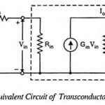
Transconductance Amplifier – Definition and Equivalent Circuit: In transconductance amplifiers the input signal is a voltage and its output signal is a current. The ideal transconductance amplifier provides an output current which is proportional to the signal voltage and the proportionality … (Read More)
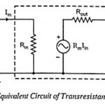
Transresistance Amplifier – Definition and Equivalent Circuit: In transresistance amplifiers the input signal is current and the output signal is voltage. The ideal transresistance amplifier provides an output voltage in proportion to the signal current, and the proportionality constant is independent … (Read More)
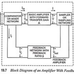
Feedback Amplifier – Block Diagram, Definition, Operation and Types: Figure 19.7 represents the block diagram of an Feedback Amplifier. The output quantity (either voltage or current) is sampled by means of a suitable sampling network (or sampler) and is fed to … (Read More)
Advantages of Negative Feedback Amplifier: There are numerous advantages of negative feedback amplifier which outweigh its only drawback of reduction in gain. Among the advantages are : 1. Gain Stability: The voltage gain of an amplifier with negative feedback is given as … (Read More)
Characteristics of Negative Feedback Amplifiers: The Characteristics of Negative Feedback Amplifiers are given below Stabilization of Gain With Negative Feedback: The variations in temperature, supply voltages, ageing of components or variations in transistor parameters with replacement are some of the factors that affect … (Read More)

Effect of Negative Feedback on Input Impedance: High input impedance is always desirable in an amplifier as it will not load the preceding stage or the input voltage source. Such a desirable characteristic can be had with the help of negative … (Read More)
Effect of Negative Feedback on Output Impedance: Just as high input impedance is advantageous to an amplifier, so is low output impedance. With lower output impedance, the amplifier is better suited to drive a low impedance load. Such a desirable characteristic … (Read More)
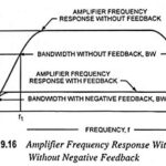
Effect of Negative Feedback on Bandwidth: The effect of negative feedback on bandwidth is given below as From Eq. (19.8) voltage gain with feedback is given as and from the above result it may be concluded that the voltage gain may be made … (Read More)
Voltage Series Feedback Amplifier or Shunt Derived Series Fed Feedback Amplifier: Voltage Series Feedback Amplifier Circuit is also called the shunt-derived series-fed feedback. Here the amplifier and feedback network are connected in series-parallel. A fraction of the output voltage is applied … (Read More)
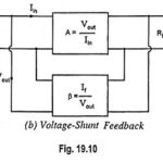
Voltage Shunt Feedback Amplifier Circuit: Voltage Shunt Feedback Amplifier Circuit is also known as shunt-derived shunt fed feedback or voltage shunt inverse feedback. Here, a small portion of the output voltage is coupled back to the input voltage, as shown in … (Read More)
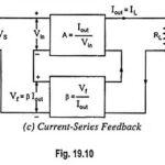
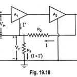
Current Series Feedback Amplifier Circuit: Current Series Feedback Amplifier Circuit is also known as series-derived series fed feedback. In such a feedback circuit, a part of the output current is made to develop a voltage proportional to the output current and … (Read More)
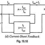
Current Shunt Feedback Amplifier Circuit: Current Shunt Feedback Amplifier Circuit is also known as series-derived shunt fed feedback or current shunt inverse feedback. In this circuit, the feedback network picks up a part of the output current and produces a feedback … (Read More)
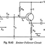
Emitter Follower Circuit – Operation, Advantages and Applications: Emitter Follower Circuit is also a negative current feedback circuit. This circuits exhibits a large input impedance, a small output impedance, and a voltage gain of approximately unity. Further the output voltage tends … (Read More)
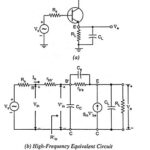
Emitter Follower at High Frequencies: Emitter Follower at High Frequencies circuit is given in Fig. 19.48(a). A capacitance CL is included across the load because the emitter follower is often used to drive capacitive loads. This is because of its small … (Read More)
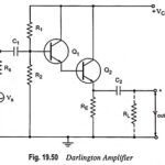
Darlington Amplifier – Circuit Diagram, Characteristics, Merits and Applications: Darlington amplifier with voltage divider bias is shown in Fig. 19.50. In this circuit the output of one amplifier is coupled into the input of the next one by directly joining emitter … (Read More)
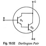
Darlington Pair Transistor – Circuit Diagram and its Workings: A very popular connection of two BJTs for operation as one “superbeta” transistor is the Darlington connection. In practice, the two transistors are put inside a single package and three terminals E, … (Read More)
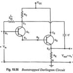
Bootstrapped Darlington Circuit Operation and its Equivalent Circuit: The maximum input resistance of a Darlington circuit is limited to 1/hob ≡ 2 MΩ, as 1/hob is the resistance between base and collector. However, the input resistance can be largely increased by … (Read More)
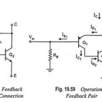
Feedback Pair Connection – Operation and its Equivalent Circuit: The feedback pair connection (Fig. 19.58) is a two-transistor circuit that operates like the Darlington amplifier. It makes use of a PNP transistor driving an NPN transistor, the two devices acting much … (Read More)