Feedback Control in Drive System:
Feedback Control in Drive System – A closed loop control of a variable speed drive system employing thyristor power converters is normally a discrete time system when a microprocessor is implemented for control purposes The system may be linear or non-linear
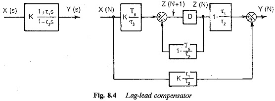
The power converter itself is a discrete time system due to switching of the thyristors. Just as a continuous system is represented by differential equations and Laplace transform, a discrete data system can be represented by difference equations and Z-transform. The state space equations are difference equations. The speed loop and current loop have their own time constants and sampling frequencies. The system has multirate sampling. Compared to these the sampling rate of the converter is negligible. The state variable feedback may be employed using the state space techniques which can be applied to both linear and nonlinear systems. The controllers for such feedback control of a variable speed system are shown in Figs 8.3 and 8.4.
The microprocessor may be programmed, to implement the necessary controllers and limiters. These also have their own sampling rates. The compensators in the current and speed loops are introduced to improve the behaviour of the system. These are normally PI, PID, or lag-lead compensators. In the hardware oriented system using discrete analog components, a controller is specified by its transfer function in Laplace transform. In digital control using either digital components or microprocessors, a controller is developed based on its time domain difference equations.
The Laplace transfer function of an analog controller must be suitably transformed to time domain difference equations to develop an equivalent digital controller.
A microprocessor based compensator has the following features:
- It is cheaper than its analog counterpart.
- It offers advanced control capacity. Adaptive control is possible.
- It offers significant flexibility. The control parameter or even control algorithm can be changed.
- It is more compact and lighter than its analog counterpart. Its power consumption is also small.
- It is highly reliable because the number of components is less and mainly supported by software. The noise is also less.
The digital implementation of PI, and lag-lead compensators is shown in Figs 8.3 and 8.4. The equivalent analog compensators are also shown.
The analog compensators limit the output to a safe value as desired due to the inherent saturation present. This limiting of the control variables is required in the closed loop control system so that the overloading of the components is prevented. The control variables are not allowed to have excursions beyond these limits. In a microprocessor based controller these limits are stored in the memory. Thus the limiting properties of a microprocessor based compensator are adaptable to any operating conditions by changing the values in the memory.

