Filters in Network Analysis Articles:
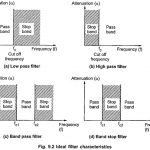
Ideal Filter Characteristics: The range of frequencies over which attenuation by filter is zero is called pass band. The range of frequencies over which attenuation is infinite is called stop band or attenuation band of the filter. The frequencies … (Read More)
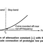
Filter Fundamentals in Network Analysis: The complete study of behavior of any filter section needs calculations of its characteristic impedance (Z0), propagation constant (γ), attenuation constant (α) and phase constant (β), using advanced mathematical calculations … (Read More)
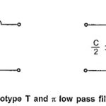
Low Pass Filter: The prototype T and π low pass filter sections are as shown in the Fig. 9.3. Design Impedance (R0): Here in low pass filter sections, Total series arm impedance Z1 = jωL Total shunt arm impedance Z2 = -j/ωC Hence, Z1 . Z2 = (jωL) (-j/ωC) … (Read More)
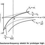
High Pass Filter: The prototype high pass filter T and π sections are as shown in the Fig. 9.9. Design Impedance (R0): Total series arm impedance Z1 = -j/ωC Total shunt arm impedance Z2 = jωL Hence, Z1 . Z2 =(-j/ωC) (jωL) = L/C which is real and … (Read More)
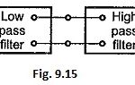 Band Pass Filter: Band pass filter pass a certain range of frequencies (called as pass band) while attenuate all other frequencies. Such band pass filters can be obtained by connecting low pass filter sections in cascade with high pass filter sections … (Read More)
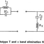
Band Stop Filter: Band Stop Filter stop a range of frequencies between two cut-off frequencies f1 and f2 while pass all the frequencies below f1 and above f2. Thus range of frequencies between f1 and f2 constitutes a stop band in … (Read More)
m Derived Filters: The first disadvantage of prototype filter sections can be overcome by connecting two or more prototype sections of same type (either all T type or all π type) in cascade. In such a cascade … (Read More)
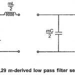
m Derived Low Pass Filter: The m Derived Low Pass Filter T and π sections are as shown in the Fig. 9.29 (a) and (b) respectively. Consider that the shunt arm of T section resonates at the frequency of infinite attenuation i.e. … (Read More)
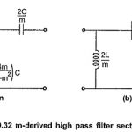
m Derived High Pass Filter: The m Derived High Pass Filter T and π sections are as shown in the Fig. 9.32 (a) and (b). Consider that the shunt arm of the T section resonates at a frequency of infinite attenuation i.e. … (Read More)
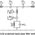
m Derived Band Pass Filter: We can obtain m Derived Band Pass Filter if the prototype band pass filter is simplified according to the network in the Fig. 9.35 which has been used to obtain m-derived low pass and high pass … (Read More)
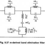
m Derived Band Stop Filter: The m Derived Band Stop Filter can be derived from the prototype band elimination filter section in the exactly same way as the m-derived band pass filter. The m Derived Band Stop Filter section is as shown … (Read More)
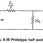
Impedance Matching using Half Sections: While connecting number of different sections in the filter, it is very important to match the impedances of the sections at the junction points. Thus a T section should not be connected to a π section … (Read More)
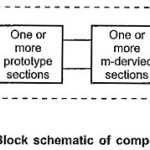
Composite Filters in Network Analysis: In prototype filter sections, the attenuation characteristic is not very sharp in the attenuation band as it is expected. This drawback can be overcome by using m-derived filter sections which … (Read More)
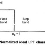
Normalized Low Pass Filter Characteristics: The passive filters are the filters consisting only passive components such as resistors, inductors, capacitors. These classical filters are designed starting with filter networks such as T type, Π type … (Read More)
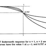
Butterworth Approximation: In low-pass filter design, we have to assume that all transmission zeros of the system function are at infinity. Then the magnitude function in general form can be written as, Where k is called as dc gain … (Read More)
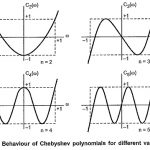
Chebyshev Approximation: In the earlier section, we have studied that the Butterworth approximation is the best at ω = 0. But as we move towards cut-off frequency, ωc = 1, approximation becomes poorer. It departs from ideal characteristics. Let us … (Read More)