Finite Impulse Response Filters Interview Questions and Answers:
1. What are the different types of filters based on impulse response?
Ans. Based on impulse response the filters are of two types 1. IIR filter 2. FIR filter
IIR filter – The IIR filters are of recursive type, whereby the present output sample depends on the present input, past input samples and output samples.
FIR filter – The FIR filters are of non recursive type whereby the present output sample is depend on the present input sample and previous input samples.
2. What are the different types of filters based on frequency response?
Ans. The filters can be classified based on frequency response. They are
- Lowpass filter
- Highpass filter
- Bandpass filter
- Bandreject filter.
3. What is the most general form of IIR filter?
Ans. The most general form of IIR filter can be written as
where at least one of the ak is non zero and all the roots of the denominator are not cancelled by the roots of the numerator.
4. What are the desirable and undesirable features of FIR filters? OR What are the advantages and disadvantages of FIR filters?
Ans.
Advantages
- FIR filters have exact linear phase.
- FIR filters are always stable.
- FIR filters can be realized in both recursive and non recursive structure.
- Filters with any arbitrary magnitude response can be tackled using FIR frequency.
Disadvantages
- For the same filter specifications the order of FIR filter design can be as high as 5 to 10 times that in a IIR design.
- Large storage requirements needed.
- Powerful computational facilities required for the implementation.
5. Distinguish between FIR and IIR filters.
Ans.
| Sl no | FIR filter | IIR filter |
| 1 | These filters can be easily designed to have perfectly linear phase. | These filters do not have linear phase. |
| 2 | FIR filters can be realized recursively and non-recursively. | IIR filters are easily realized recursively. |
| 3 | Greater flexibility to control the shape of their magnitude response. | Less flexibility, usually limited to specific kind of filters. |
| 4 | Errors due to roundoff noise are less severe in FIR filters, mainly because feedback is not used. | The round off noise in IIR filters are more. |
6. What are the design techniques of designing FIR filters?
Ans. There are three well-known methods for designing FIR filters with linear phase. These are
- Windows method
- Frequency sampling method
- Optimal or minimax design.
7. What do you understand by linear phase response?
Ans. For a linear phase filter θ(ω) α ω. The linear phase filter did not alter the shape of the original signal. If the phase response of the filter is non linear the output signal may be distorted one. In many cases a linear phase characteristic is required throughout the passband of the filter to preserve the shape of a given signal with in the passband. IIR filter cannot produce a linear phase. The FIR filter can give linear phase, when the impulse response of the filter is symmetric about its mid point.
8. For what kind of applications, the antisymmetrical impulse response can be used?
Ans. The antisymmetrical impulse response can be used to design Hilbert transformers and differentiators.
9. For what kind of application, the symmetrical impulse response can be used?
Ans. The impulse response, which is symmetric having odd number of samples can be used to design all types of filters, i.e., lowpass, highpass, bandpass and bandreject.
The symmetric impulse response having even number of samples can be used to design lowpass and bandpass filter.
10. What is the reason that FIR filter is always stable?
Ans. FIR filter is always stable because all its poles are at the origin.
11. What condition on the FIR sequence h(n) are to be imposed in order that this filter can be called a linear phase filter?
Ans. The conditions are
- Symmetric condition h(n) = h(N – 1 – n)
- Antisymmetric condition h(n) = -h(N – 1 – n).
12. State the condition for a digital filter to be causal and stable.
Ans.
A digital filter is causal if its impulse response h(n) = 0 for n < 0.
A digital filter is stable if its impulse response is absolutely summable, i.e.,
13. What are the properties of FIR filter?
Ans.
- FIR filter is always stable.
- A realizable filter can always be obtained.
- FIR filter has a linear phase response.
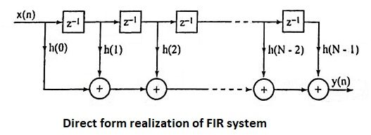
14. Draw the direct form realization of FIR system.
Ans.
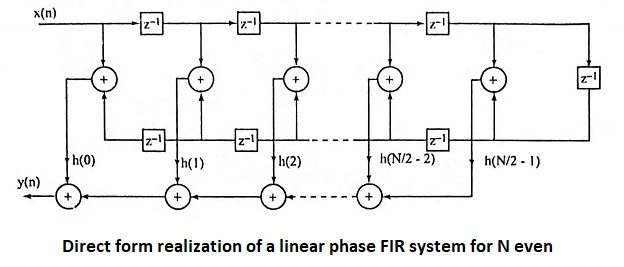
15. Draw the direct form realization of a linear phase FIR system for N even.
Ans.
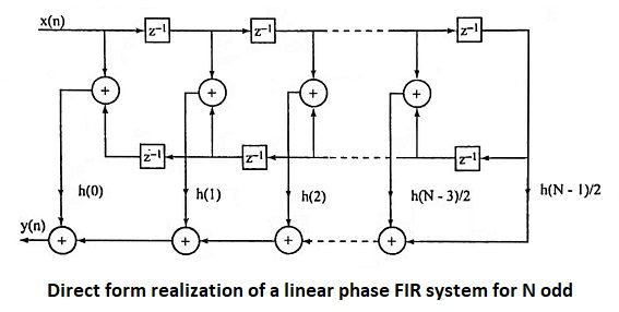
16. Draw the direct form realization of a linear phase FIR system for N odd.
Ans.
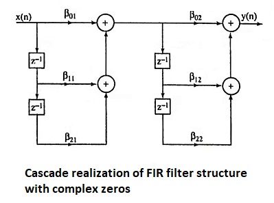
17. Give the cascade realization of FIR filter structure with complex zeros
Ans.
Let H(z) is having 4 complex zeros where |z| < 1. Then we can write
This can be realized as
18. When cascade form realization is preferred in FIR filters?
Ans. The cascade form realization is preferred when complex zeros with absolute magnitude less than one.
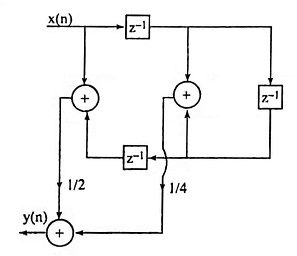
19. Obtain direct form realization with minimum number of multipliers.
Ans.
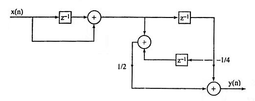
20. Obtain cascade realization with minimum number of multipliers
Ans.
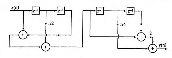
21. Obtain cascade realization using the minimum number of multipliers.
Ans.
22. What is the basis for Fourier series method of design? Why truncation is necessary?
Ans. The frequency response H(ejω) of any digital filter is periodic in frequency, can be expanded in a Fourier series
where the Fourier coefficients are
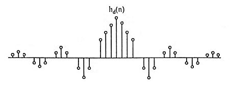
h(n) is of infinite duration, hence, the filter resulting from a Fourier series representation of H(ejω) is an unrealizable IIR filter. To get an FIR filter that approximates H(ejω) would be to truncate the infinite Fourier series at N = ± (N-1/2).
23. Explain briefly the method of designing FIR filter using Fourier series method.
Ans.
- For the desired frequency response Hd(ejω), find closed form expression for h(n) using the equation.
- Truncate hd(n) at n = ± (N-1/2) to get the finite duration sequence h(n).
- Find H(z) using the equation
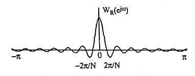
- The central lobe of the frequency response of the window should contain most of the energy and should be narrow.
- The highest side lobe level of the frequency response should be small.
- The side lobes of the frequency response should decrease in energy rapidly as ω tends to π.
| Sl no | Hamming window | Kaiser window |
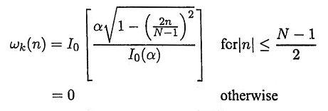
| 1 | The main lobe width is equal to 8π/N and the peak side lobe level is -41 dB. | The main lobe width, the peak side lobe level can be varied by varying the parameters α and N. |
| 2 | The low pass FIR filter designed will have first side lobe peak of -53 dB | The side lobe peak can be varied by varying the parameter α. |
- It provides flexibility for the designer to select the side lobe level and N.
- It has the attractive property that the side lobe level can be varied continuously from the low value in the Blackman window to the high value in the rectangular window.


