Fluorescent Tube – Definition, Construction, Working, Merits and Demerits:
Fluorescent lighting has a great advantage over other light sources in many applications. The tubes can be obtained in a variety of lengths, with illumination in a variety of colours. It is possible to achieve quite high lighting intensities without excessive temperature rise and, owing to the nature of light sources, the danger of glare is minimised. It must not, however, be thought that fluorescent lamps can be used indiscriminately without giving careful consideration to the type of reflector to be employed or to the correct positioning of the light source. An exposed tube in the line of vision is usually as bad as a tungsten lamp would be. The efficiency of fluorescent tube is about 40 lumens per watt, about three times the efficiency of an equivalent tungsten filament lamp. The fluorescent tube consists of a glass tube 25 mm in diameter and 0.38 m-1.52 m in length. The inside surface of the tube is coated with a thin layer of fluorescent material in the form of a powder.
The coating materials used depend upon the colour effect desired and may consist of zinc silicate, cadmium, silicate or calcium tungstate. These organic chemicals are known as phosphors which transforms short-wave invisible radiations into visible light. By mixing the various powders light of any desired colour including day light can be obtained. The tube contains small quantity of argon gas at a pressure of 2.5 mm of mercury and one or two drops of mercury. It is provided with two electrodes coated with electron emissive material. A starting switch is provided in the circuit, which puts the electrodes directly across the supply mains at the time of starting, so that electrodes may get heated and emit sufficient electrons. A stabilising choke is connected in series with it, which acts as a ballast in running condition and provides a voltage impulse for starting. A capacitor is connected across the circuit to improve the power factor.
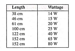
Fluorescent tubes are available in the following sizes :
The fluorescent lamp in common with most electrical devices may cause a certain amount of radio interference. This interference may be caused due to one of the following factors :
- Direct radiation from the bulb to the antenna. This effect diminishes rapidly as the radio is separated from the lamp. Thus, for example, at a radius of 2.8 metres interference from this cause is negligible.
- Line radiation from the electric supply line to the antenna.
- Lint feedback from the lamp through the line to the radio.
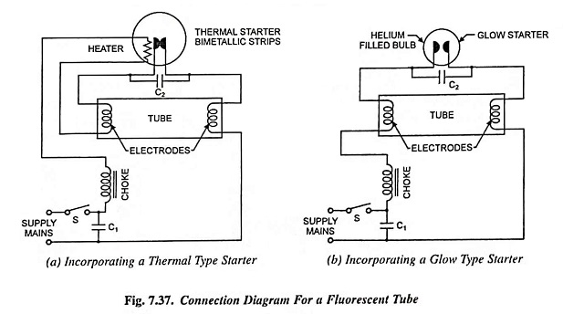
The radio interference effect may be reduced to a minimum by connecting a small capacitor (0.05 μF) across starter terminals, as shown in Figs. 7.37 (a) and 7.37 (b).
The starting switches are of two types, namely the thermal type and the glow type.
The connections of a fluorescent tube incorporating a thermal type starter are shown in Fig. 7.37 (a). The thermal starter is a current operated device and consists of two metallic strips and a heater coil. The bimetallic strips are in contact with each other when the lamp is not in operation. When the supply is switched on, the two electrodes get connected in series through the thermal switch, the relatively large current rising them to incandescence. The current also flows through the heater element as a result of which bimetallic strips break contact. This causes interruption in the current flowing through the circuit, which further results in a high voltage surge across the electrodes of the tube, which is enough to strike the arc between the electrodes. This arc is then maintained by the normal lamp voltage. Bombardment of the electrode’s surface by the positive mercury ions maintains their temperature so that they continue to emit electrons. Thus the tube is put in operation. The thermal switch is now generally obsolete because of its more complicated construction, greater cost and greater power loss.
The connections of a fluorescent tube incorporating a glow type starter are shown in Fig. 7.37 (b). The glow type starter is a voltage operated device and consists of two bimetallic electrodes enclosed in a glass bulb filled with a mixture of helium and hydrogen. Normally the contacts are open. When the supply is switched on, the potential across bimetallic electrodes causes a small glow discharge at a small current not enough to heat up the tube electrodes (filament). This discharge is enough, however, to heat the bimetallic strips of the switch causing them to bend and make contact. The result is a large current through the electrodes, their temperature being raised to incandescence and the gas in the immediate neighbourhood is ionised. After one or two seconds the bimetallic strips cool down and the contacts open. This opening of contacts in series with the choke causes a momentary high voltage, which is sufficient to start the discharge in the main tube. The starter ceases to glow as the voltage is now too low. A small capacitor is placed inside the starter to suppress arcing and radio interference.
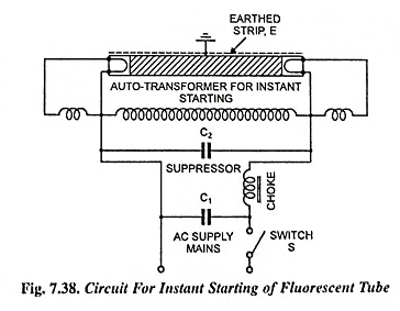
Nowadays starterless circuits, as instant start, rapid start etc. for such tubes are also employed (Fig. 7.38). The primary winding of an auto-transformer is connected in parallel with the tube and receives practically full mains voltage. The filaments arc provided with current from secondary tappings. When the lamp has started the transformer receives the normal tube voltage and the filament currents are correspondingly reduced.
Stroboscopic Effect: At the usual alternating current supply frequency of 50 Hz, a discharge lamp will be extinguished 100 times per second. Although this effect is seldom noticeable in normal conditions. It is possible that this may, in some instances, give rise to a stroboscopic effect, that is moving objects such as rotating parts of machinery, illuminated by this light, may appear to be moving in disunity or jerks, or rotating more slowly than their actual speed.
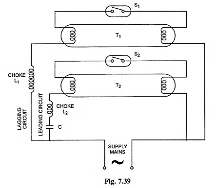
In actual applications, however, where this effect might cause annoyance, it can be practically eliminated in a three lamp unit by connecting each lamp on a separate phase of a 3-phase system and it can be greatly reduced in a two lamp unit by the use of a two lamp control unit, which employs a condenser in the ballast of one of the lamps. (Fig. 7.39). The current through the lamps is almost 90° out of phase and under these conditions light output of one of the lamps is at a maximum. This method has an additional advantage of giving an overall power factor of nearly unity for the unity of two lamps. In this arrangement one circuit remains at a low power factor at about 0.5 lagging, while the other circuit incorporating a series capacitor C remains at a power factor of about 0.5 leading.
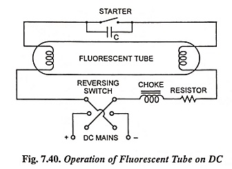
Fluorescent Lamps For DC Supply: In the foregoing discussions, it has been assumed that the supply to the fluorescent tube is ac. If however, the available supply is dc some special accessories and circuit modification will be required.
- The choke coil has a low impedance on dc and therefore, a ballast resistance is connected in series with the choke in order to limit the current.
- On systems below 220 V. starting becomes less certain on dc. Only thermal type starters should be used.
- The positive end becomes relatively dark on account of the tendency of the mercury vapour to migrate towards the negative end of the tube. In order to overcome this defect a reversing switch is included in the circuit between the supply and the fitting, as shown in Fig. 7.40.
In dc operation of fluorescent tube there is no problem of power factor correction and no stroboscopic effect. Its disadvantages are—low efficiency due to power loss in ballast series resistance, increased cost of the ballast resistance and reversing switch and less life of the tube (about 80% of that with ac operation).
Colour of Fluorescent Light: As already mentioned the colour of fluorescent light depends upon the fluorescent powder used and the vapour pressure in the lamp. A few important variations of white colour with their applications are given below.
- Daylight: This is suitable for industrial applications where checking of material is carried out at high illumination levels (say 1,000 lux or more) and for normal lighting service.
- Warm-White: This is mostly used for street lighting where colour rendition, due to low level of lighting (say 10 lux or less), is of little importance.
- Warm-White Deluxe: It is used for illuminating rooms of large gathering such as shops, restaurants, and dwelling houses. It combines well with the light of incandescent lamps, as in show-windows etc.
- White: It is useful for use in offices, drawing offices, schools and factories. It harmonizes exceptionally well with the daylight, and therefore, light is a good supplement to daylight.
White-Deluxe: It is very suitable for use in offices, schools and shops where colour rendition is important.
Useful Lamp Life: In general, fluorescent lamps lose their usefulness because of reduction in light output before they fail to operate. Darkening of the bulb occurs because of the effect of mercury on the fluorescent coating and because of the material given off by the electrodes. The latter specially causes darkening at the ends of the bulb late in life. The rate of depreciation in light output diminishes throughout the life; the first hundred hours produce approximately as much darkening as the following 1,000 hours. Rated output is based on conditions at 100 hours.
Frequent starting of lamps may take more life out of the electrodes than long hours of burning because momentarily there is a higher than normal voltage drop at the electrodes which causes the active material to sputter or evaporate off. If a lamp be started once a minute, for example, the hours of burning will be shorter than normal, but if it be switched on and burned continuously, its life will be longer than normal. When the active material on the electrodes is nearly exhausted, the voltage required for starting will rise and may equal or exceed the available supply. This may occur after the lamp has been started thousands of times or burned beyond its rated life. Sometimes the end of life is indicated by the lamp flashing momentarily and then going out.
The normal life of a fluorescent lamp is 7,500 hours. The average life is for three burning hours per switching operation. The actual life may vary from 5,000 to 10,000 hours depending upon the operating conditions. Light output is reduced by 15-20% after 4,000 hours of operation and it is, therefore, a good practice to replace the fluorescent lamp after 4,000-5,000 hours burning on economical grounds.
Performance Curves:
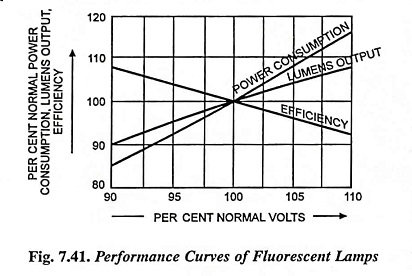
Performance curves are shown in Fig. 7.41.
The effect of voltage variation in the case of fluorescent lamps is less marked as compared to the incandescent lamps. However, their life and performance arc adversely affected both by low and high voltage. With increased voltage there is a greater heating of electrodes and they lose emissive material by evaporation. With reduced voltage, the current reduces causing sputtering at the electrodes shortening their life.
The best performance of fluorescent lamps is obtained at 20-25°C operating temperature. It decreases rapidly when a lamp is operated at a lower temperature or is exposed to cold wind drafts. The fluorescent lamps may be enclosed in outer envelops for their protection from cold weather in exposed locations. For operation at high temperature, the fittings with provision for air circulation should be employed.
Operating Instructions:
- A fluorescent lamp should start up with little blinking. Blinking indicates a defective starter, low voltage or a defective tube. Both the choke and the starter will get damaged due to overheating, if this condition is allowed to persist. The tube or the starter must be replaced immediately.
- Correct voltage must be ensured.
- The starter should be replaced every time a tube is changed. A bad starter shortens the life of the tube.
- Frequent switching operations should be avoided.
Merits and Demerits:
As already stated the fluorescent lamps have got merits of high luminous efficiency, long life, low running cost, low glare level and less heat output. The demerits are stroboscopic effect, small wattage requiring large number of fittings and magnetic hum associated with the choke causing disturbance. The problem of noise can be solved to some extent by mounting chokes on resilient pads.
