Flux Linkages of an Isolated Current Carrying Conductor:
Transmission lines are composed of parallel conductors which, for all practical purposes, can be considered as infinitely long. Let us first develop expressions for flux linkages of a long isolated Current Carrying Conductor with return path lying at infinity. This system forms a single-turn circuit, flux linking which is in the form of circular lines concentric to the conductor. The total flux can be divided into two parts, that which is internal to the conductor and the flux external to the conductor. Such a division is helpful as the internal flux progressively links a smaller amount of current as we proceed inwards towards the centre of the conductor, while the external flux always links the total current inside the conductor.
Flux Linkages due to Internal Flux:
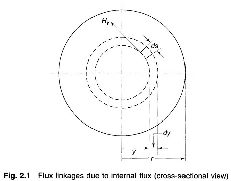
Figure 2.1 shows the cross-sectional view of a long cylindrical Current Carrying Conductor I.
The mmf round a concentric closed circular path of radius y internal to the conductor as shown in the figure is
where
- Hy = magnetic field intensity (AT/m)
- Iy = current enclosed (A)
By symmetry, Hy is constant and is in direction of ds all along the circular path. Therefore, from Eq. (2.8) we have
Assuming uniform current density
From Eqs. (2.9) and (2.10), we obtain
The flux density By, y metres from the centre of the conductors is
where μ is the permeability of the conductor.
Consider now an infinitesimal tubular element of thickness dy and length one metre. The flux in the tubular element dΦ = By dy webers links the fractional turn (Iy/I = y2/r2) resulting in flux linkages of
Integrating, we get the total internal flux linkages as
For a relative permeability μr = 1 (non-magnetic conductor), μ = 4π x 10-7H/m, therefore
and
Flux Linkage due to Flux Between Two Points External to Conductor:
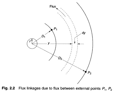
Figure 2.2 shows two points P1 and P2 at distances D1 and D2 from a conductor which carries a current of I amperes. As the conductor is far removed from the return current path, the magnetic field external to the conductor is concentric circles around the conductor and therefore all the flux between P1 and P2 lines within the concentric cylindrical surfaces passing through P1 and P2.
Magnetic field intensity at distance y from the conductor is
The flux dΦ contained in the tubular element of thickness dy is
The flux dΦ being external to the conductor links all the Current Carrying Conductor which together with the return conductor at infinity forms a single return, such that its flux linkages are given by
Therefore, the total flux linkages of the conductor due to flux between points P1 and P2 is
where In stands for natural logarithm.
Since μr=1, μ = 4πx10-7
The inductance of the Current Carrying Conductor contributed by the flux included between points P1 and P2 is then
Flux Linkages due to Flux up to an External Point:
Let the external point be at distance D from the centre of the conductor. Flux linkages of the conductor due to external flux (from the surface of the conductor up to the external point) is obtained from Eq. (2.17) by substituting D1 = r and D2 = D, i.e.,
Total flux linkages of the conductor due to internal and external flux are
Let
Inductance of the conductor due to flux up to an external point is therefore
Here r’ can he regarded as the radius of a fictitious conductor with no internal inductance but the same total inductance as the actual conductor.


