PLL FM Detector or Demodulator:
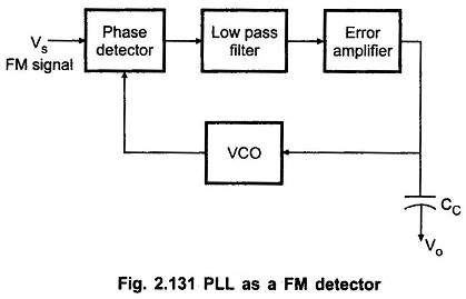
The PLL can be very easily used as an FM detector or demodulator. Fig. 2.131 shows the PLL FM Detector or Demodulator Block Diagram.
When the PLL is locked in on the FM signal, the VCO frequency follows the instantaneous frequency of the FM signal, and the error voltage or VCO control voltage is proportional to the deviation of the input frequency from the centre frequency.
Therefore, the a-c component of error voltage or control voltage of VCO will represent a true replica of the modulating voltage that is applied to the FM carrier at the transmitter.
The faithful reproduction of modulating voltage depends on the linearity between the instantaneous frequency deviation and the control voltage of VCO. It is also important to note that the FM frequency deviation and the modulating frequency should remain in the locking range of PLL to get the faithful replica of the modulating signal.
If the product of the modulation frequency fm and the frequency deviation exceeds the (Δfc)2, the VCO will not be able to follow the instantaneous frequency variations of the FM signal.
