Foldback Current Limiting Circuit:
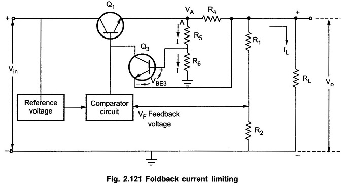
The disadvantage of constant current limit is relatively large power dissipation in the series pass transistor when the load terminals are shorted. Thus a large power rating transistor is required. The Foldback Current Limiting technique allows us to provide the necessary load current at rated voltage but reducing the short circuit current. Thus the series pass transistor gets utilized efficiently. The basic Foldback Current Limiting is shown in the Fig. 2.121.
All the voltages measured in Foldback Current Limiting circuit with respect to a common point.
Let the voltage at point A be VA and the current flowing through R4 is almost IL.
Neglecting the base current of Q3, the current flowing through R5 and R6 is same as I.
Hence the voltage at the base of Q3 is the voltage across R6.
Let
The voltage at the emitter of Q3 is
Thus if the output terminals are shorted, the output voltage Vo reduces to zero. Hence we get from the equation (9),
The rated current can be written as,
The rated load current IL is also called Iknee known as knee current.
It can be observed from the equation (11) that the rated load current is more than the short circuit current. Thus when the output terminals are shorted, the current decreases rather than increasing. Thus the series pass transistor Q1 gets protected automatically.
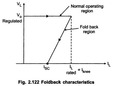
The ratio of rated load current and the short circuit current can be adjusted by selecting proper value of k. Typically k is selected to produce a maximum load current of 2 to 3 times the short circuit load current. The foldback characteristics which is the graph of the load voltage against load current is shown in the Fig. 2.122.
As seen from the characteristics, beyond the rated value, if the load increases, the voltage folds backward and finally becomes zero at ISC which is less than the rated load current. Hence the protection circuit is called foldback protection circuit.


