Fundamentals of Transmission Lines:
Fundamentals of Transmission Lines (in the context of this book) are considered to be impedance-matching circuits designed to deliver power (RF) from the transmitter to the antenna, and maximum signal from the antenna to the receiver. From such a broad definition, any system of wires can be considered as forming one or more transmission lines. If the properties of these lines must be taken into account, the lines might as well be arranged in some simple, constant pattern. This will make the properties much easier to calculate, and it will also make them constant for any type of transmission line. All practical Fundamentals of Transmission Lines are arranged in some uniform pattern. This simplifies calculations, reduces costs and increases convenience.
There are two types of commonly used Fundamentals of Transmission Lines. The parallel-wire (balanced) line is shown in Figure 7-1b, and the coaxial (unbalanced) line in Figure 7-1a.
The parallel-wire line is employed where balanced properties are required: for instance, in connecting a folded-dipole antenna to a TV receiver or a rhombic antenna to an HF transmitter. The coaxial line is used when unbalanced properties are needed, as in the interconnection of a broadcast transmitter to its grounded antenna. It is also employed at UHF and microwave frequencies, to avoid the risk of radiation from the transmission line itself.
Any system of conductors is likely to radiate RF energy if the conductor separation approaches a half-wavelength at the operating frequency. This is far more likely to occur in a parallel-wire line than in a coaxial line, whose outer conductor surrounds the inner one and is invariably grounded. Parallel-wire lines are never used for microwaves, whereas coaxial lines may be employed for frequencies up to at least 18 GHz. We know that waveguides also have frequency limitations. From the general point of view the limit is on the lowest usable frequency; below about 1 GHz, waveguide cross-sectional dimensions become inconveniently large. Between 1 and 18 GHz, either waveguides or coaxial lines are used, depending on the requirements and application, whereas waveguides are not normally used below 1 GHz, and coaxial lines are not normally used above 18 GHz.
Description:
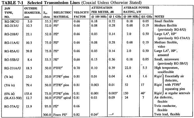
Within each broad grouping or type of Fundamentals of Transmission Lines there is an astonishing variety of different kinds, dictated by various applications. A browse through a manufacturer’s catalog will graphically illustrate this point. It invariably shows, as does Table 7-1 for a number of lines, the different forms of lines and connectors, together with their characteristics, ratings and applications. Lines may be rigid or flexible, air-spaced or filled with different dielectrics, with smooth or corrugated conductors as the circumstances warrant. Different diameters and properties are also available. Flexible lines may be more convenient than rigid ones, since they may be bent to follow any physical layout and are much easier to stow and transport. Rigid cables can generally carry much higher powers, and it is easier to make them air-dielectric rather than filled with a solid dielectric. This consideration is important, especially for high powers, since all solid dielectrics have significantly higher losses than air, particularly as frequencies are increased.
Rigid coaxial air-dielectric lines consist of an inner and outer conductor with spacers of low-loss dielectric separating the two every few centimeters, There may be a sheath around the outer conductor to prevent corrosion, but this is not always the case. A flexible air-dielectric cable generally has corrugations in both the inner and the outer conductor, running at right angles to its length, and a spiral of dielectric material between the two.
The power-handling ability of a Fundamentals of Transmission Lines is limited by the flashover distance between the conductors due to a high-voltage gradient breaking down in the dielectric. It depends on the type of dielectric material used, as well as the distance between the conductors. For the high-power cables employed in transmitters, nitrogen under pressure may be used to fill the cable and reduce flashover. Since nitrogen is less reactive than the oxygen component of air, corrosion is reduced as well. Dry air under pressure is also used as a means of keeping out moisture. As the power transmitted is increased, so must be the cross-sectional dimensions of the cable. For example, rigid air-dielectric coaxial copper cable with an outer diameter of 22.5 mm has a peak power rating of 43 kW. This increases to 400 kW for an outer diameter of 80 mm and to 3 MW for a 230-mm outer diameter. It will be shown that the inner diameter must be changed along with the outer diameter, to ensure a constant value of all line properties.
Equivalent Circuit Representation:
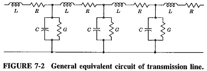
Since each conductor has a certain length and diameter, it will have a resistance and an inductance. Since there are two wires close to each other, there will be capacitance between them. The wires are separated by a medium called the dielectric, which cannot be perfect in its insulation; the current leakage through it can be represented by a shunt conductance. The resulting equivalent circuit is as shown in Figure 7-2. Note that all the quantities shown are proportional to the length of the line, and unless measured and quoted per unit length, they are meaningless.
At radio frequencies, the inductive reactance is much larger than the resistance. The capacitive susceptance is also much larger than the shunt conductance. Both R and G may be ignored, resulting in a line that is considered lossless (as a very good approximation for RF calculations). The equivalent circuit is simplified as shown in Figure 7-3.
It is to be noted that the quantities L, R, C, and G, shown in Figures 7-2 and 7-3, are all measured per unit length, e.g., per meter, because they occur periodically along the line. They are thus distributed throughout the length of the line. Under no circumstances can they be assumed to be lumped at any one point.
Characteristic Impedance:
Any circuit that consists of series and shunt impedances must have an input impedance. For the Fundamentals of Transmission Lines this input impedance will depend on the type of line, its length and the termination at the far end. To simplify description and calculation, the input impedance under certain standard, simple and easily reproducible conditions is taken, as the reference and is called the characteristic impedance of that line. By definition, the characteristic impedance of a transmission line, Z0, is the impedance, measured at the input of this line when its length is infinite. Under these conditions the type of termination at the far end has no effect, and consequently is not mentioned in the definition.
Methods of calculation It can now be shown that the characteristic impedance of a line will be measured at its input when the line is terminated at the far end in an impedance equal to Z0 ( Zin = Zout max power transfer), no matter what length the line has. This is important, because such a situation is far easier to reproduce for measurement purposes than a line of infinite length.
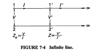
If a line has infinite length, all the power fed into it will be absorbed. It should be fairly obvious that as one moves away from the input, voltage and current will decrease along the line, as a result of the voltage drops across the inductance and current leakage through the capacitance. From the meaning of infinity, the points 1′-2′ of Figure 7-4 are just as far from the far end of this line as the points 1-2. Thus the impedance seen at 1′-2′ (looking to the right) is also Z0, although the current and voltage are lower than at 1-2. We can thus say that the input terminals see a piece of line up to 1′-2′, followed by a circuit which has the input impedance, equal to Z0. It quite obviously does not matter what the circuit to the right of 1′-2′ consists of provided that it has an input impedance equal to the characteristic impedance of the line. Z0 will be measured at the input of a transmission line if the output is terminated in Z0. Under these conditions Z0 is considered purely resistive.
It follows from filter theory that the characteristic impedance of an iterative circuit consisting of series and shunt elements is given by
where
Z = series impedance per section
= R + jωL (Ω/m here) and is the series impedance per unit length
Y = shunt admittance per section
= G + jωC (S/m here) and is the shunt admittance per unit length
Therefore
From Equation (7-2) it follows that the characteristic impedance of a Fundamentals of Transmission Lines may be complex, and indeed it very often is, especially in line communications, i.e., telephony at voice frequencies. At radio frequencies the resistive components of the equivalent circuit become insignificant, and the expression for Z0 reduces to
L is measured in henrys per meter and C in farads per meter; it follows that Equation (7-3) shows the characteristic impedance of a line in ohms and is dimensionally correct. It also shows that this characteristic impedance is resistive at radio frequencies.
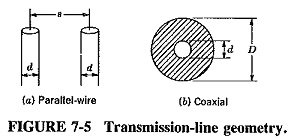
Physically, characteristic impedance is determined by the geometry, size and spacing of the conductors, and by the dielectric constant of the insulator separating them. It may be calculated from the following formulas, the various terms having meanings as shown in Figure 7-5:
For the parallel-wire line, we have
For the coaxial line, this is
where
k = dielectric constant of the insulation.
Note that the figure 138 is equal to 120π/e, where 120π = 377 Ω. is the impedance of free space, and e is the base of the natural logarithm system; 276 is 2 x 138.
Equation (7-4) appears to take no account of the dielectric constant of the insulating material. This is because the material is very often air for parallel-wire lines, and its dielectric constant is unity. The formula for the Z0 of a balanced line with solid dielectric is almost identical, except that the first term becomes 276/√k.
The usual range of characteristic impedance for balanced lines is 150 to 600 Ω, and 40 to 150 Ω for coaxial lines, both being limited by their geometry.


