Generator Inter Turn Fault Protection:
Merz-Price circulating current protection system does not provide protection against turn-to-turn faults (short circuits between the turns) on the same phase winding of the stator because the current produced by such a fault flows in a local circuit between the turns involved and does not create the difference between the currents entering and leaving the winding at its two ends where the CTs are mounted. However, it is usually considered unnecessary to provide such a protection since short circuits between the turns on the same phase invariably develop into earth fault.
The coils of modern large turbogenerators are usually single turn and hence they do not need turn-to-turn protection. However, Generator Inter Turn Fault Protection is provided for multi-turn generators such as hydroelectric generators. In case of large generators, stator windings are sometimes duplicated in order to carry heavy current. Advantage may be taken of this necessity to provide Generator Inter Turn Fault Protection. In this case the stator winding has two separate parallel paths, as illustrated in Fig. 11.9.
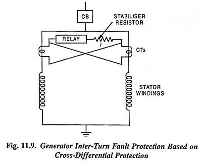
The primaries of CTs are inserted in these parallel paths and the secondaries are cross-connected, as shown in the figure. When there is no fault, currents flowing through the two parallel paths of the stator winding will be equal and therefore no current will flow through the relay operating coil. But during Generator Inter Turn Fault Protection in the phase winding, the currents flowing through the two parallel paths will be different and a current proportional to the difference of two currents will flow through the relay operating coil which will close the trip circuit and isolate the machine from the power system. Such a protection can be extremely sensitive.
Generators having single winding per phase or those generators whose parallel windings are not accessible can be protected by using zero sequence component of voltage caused by the reduction of the emf induced in the faulty phase. One such circuit is given in Fig. 11.10.
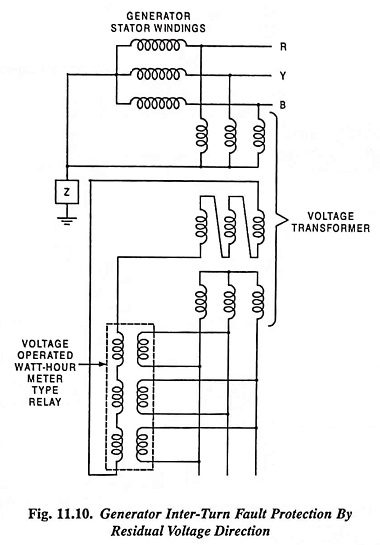
In this arrangement a voltage transformer is connected between each phase terminal and the neutral of the winding. The secondary leads are connected in an open delta. The zero sequence voltage (residual voltage of the generator terminals) appears across the tertiary winding of the voltage transformer which is connected to the operating winding of a three clement directional relay. This winding in quadrature to this operating winding of the relay is energized by the secondary of the voltage transformer. During normal operation, the residual voltage is zero i.e.,
This balance is disturbed during Generator Inter Turn Fault Protection on any of the single windings and the relay operating coil is energized by the residual voltage.