High Frequency Power Supply Working Principle:
The high frequency power supply for coreless induction furnace is usually obtained from ordinary supply system and its frequency is converted to higher value either by means of motor-generator set with salient pole alternator (suitable for frequencies up to about 1,000 Hz and for any output required) or by means of motor-generator set with inductor alternator (suitable for frequencies up to about 10,000 Hz and output of 1 tonne) or by means of valve oscillators (suitable for very small furnaces which necessitates frequencies up to 1 million Hz). The oscillator which is employed in induction heating differs from the oscillator used in radio transmitters.
The induction heaters are rugged, compact, portable and are almost automatic in operation. They are to be handled by unskilled operators and in comparatively dirty atmosphere. They are also subjected to overload and vibration. Hence while designing an oscillator for high frequency current supply for induction heating, the above factors should be given a proper consideration.
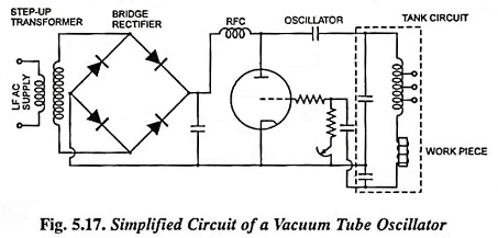
The round about value of frequency used for induction heating is 400 kHz, the circuit being used is shown in Fig. 5.17.
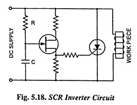
The ac supply is, stepped up by the transformer initially, the stepped up voltage is rectified by using a bridge rectifier circuit, the rectified voltage is applied to the oscillator to obtain high frequency currents. The capacitances and inductances (including that of work piece) decide the frequency of supply to work piece. The vacuum tube oscillators are less efficient as compared to SCR, the voltage drop across the SCR being very small (of the order of 1 V). The operating efficiency of SCR is about 90%. The SCRs are fired by pulses of gate current produced by a UJT. The circuit is shown in Fig. 5.18. The high frequency power supply to work piece depends upon the value of R and C. The smaller the product of R and C, higher is the frequency across the work piece.
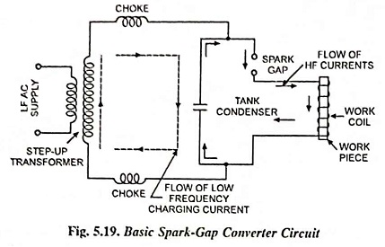
Sometimes spark gap oscillators are also employed to provide high frequency power supply. The basic principle of operation of a spark gap converter is the alternate charging and discharging of a capacitor.
The transformer step ups the voltage, say to about 500 V, the tank condenser gets a voltage build-up till the spark gap breaks down and flashover takes place. The value of inductance and capacitance in the discharge circuit decides the frequency of current through the gap. Frequencies up to 1 MHz can be obtained.


