High Voltage Test on Circuit Breaker and Isolators:
High Voltage Test on Circuit Breaker and Isolators is covered, giving common characteristics for both. While these characteristics are directly relevant to the testing of circuit breakers, they are not much relevant as far as the testing of isolators are concerned since isolators are not used for interrupting high currents. At best, they interrupt small currents of the order of 0.5 A (for rated voltages of 420 kV and below) which may be the capacitive currents of bushings, busbars etc. In fact, the definition of an Isolator or a Disconnector as per IS: 9921 (Part I)-1981 is as follows:
An isolator or a disconnector is a mechanical switching device, which provides in the open position, an isolating distance in accordance with special requirements. An isolator is capable of opening and closing a circuit when either negligible current is broken or made or when no significant change in the voltage across the terminals of each of the poles of the isolator occurs. It is also capable or carrying currents under normal circuit conditions, and carrying for a specified time, currents under abnormal conditions such as those of a short circuit.
Thus, most of the discussion here refers to the High Voltage Test on Circuit Breaker and Isolators.
High Voltage Test on Circuit Breaker and Isolators is intended to evaluate
(a) the constructional and operational characteristics, and
(b) the electrical characteristics of the circuit Which the switch or the breaker has to interrupt or make.
The different characteristics of High Voltage Test on Circuit Breaker and Isolators or a switch may be summarized as per the following groups.
- The electrical characteristics which determine the arcing voltage, the current chopping characteristics, the residual current, the rate of decrease of conductance of the arc space and the plasma, and the shunting effects in interruption.
- Other physical characteristics including the media in which the arc is extinguished, the pressure developed or impressed at the point of interruption, the speed of the contact travel, the number of breaks, the size of the arcing chamber, and the materials and configuration of the circuit interruption.
- The characteristics of the circuit include the degree of electrical loading, the normally generated or applied voltage, the type of fault in the system which the breaker has to clear, the time of interruption, the time constant, the natural frequency and the power factor of the circuit, the rate of rise of recovery voltage, the re striking voltage, the decrease in the a.c. component of the short circuit current, and the degree of asymmetry and the d.c. component of the short circuit current.
To assess the above factors, the main tests conducted on the circuit breakers and isolator switches are
- the dielectric tests or overvoltage tests
- the temperature rise tests,
- the mechanical tests, and
- the short circuit tests
Dielectric tests consist of overvoltage withstand tests of power frequency, lightning and switching impulse voltages. Tests are done for both internal and external insulation with the switch or circuit breaker in both the open and closed positions. In the open position, the test voltage levels are 15% higher than the test voltages used when the breaker is in closed position. As such there is always the possibility of line to ground flashover. To avoid this, the High Voltage Test on Circuit Breaker and Isolators is mounted on insulators above the ground, and hence the insulation level of the body of the circuit breaker is raised.
The impulse tests with the lightning impulse wave of standard shape are done in a similar manner as in the case of insulators. In addition, the switching surge tests with switching overvoltages are done on High Voltage Test on Circuit Breaker and Isolators and isolators to assess their performance under overvoltages due to switching operations.
Temperature rise and mechanical tests are typetests on circuit breakers and are done according to the specifications.
Short Circuit Tests:
The most important test carried out on circuit breakers are short circuit tests, since these tests assess the primary performance of these devices, i.e. their ability to safely interrupt the fault currents. These tests consist of determining the making and breaking capacities at various load currents and rated voltages. In the case of isolators, the short circuit tests are conducted only with the limited purpose to determine their capacity to carry the rated short circuit current for a given duration; and no breaking or making current tests is done.
The different methods of conducting short circuit tests are:
1.Direct Tests
- using a short circuit generator as the source
- using the power utility system’or network as the source.
2.Synthetic Tests
(a) Direct Testing in the Networks or in the Fields: High Voltage Test on Circuit Breaker and Isolators are sometimes tested for their ability to make or break the circuit under normal load conditions or under short circuit conditions in the network itself. This is done during period of limited energy consumption or when the electrical energy is diverted to other sections of the network which are not connected to the circuit under test.
The advantages of field tests are:
- The High Voltage Test on Circuit Breaker and Isolators is tested under actual conditions like those that occur in a given network.
- Special occasions like breaking of charging currents of long lines, very short line faults, interruption of small inductive currents, etc. can be tested by direct testing only.
- To assess the thermal and dynamic effects of short circuit currents, to study applications of safety devices, and to revise the performance test procedures, etc.
The disadvantages are:
- The circuit breaker can be tested at only a given rated voltage and network capacity.
- The necessity to interrupt the normal services and to test only at light load conditions.
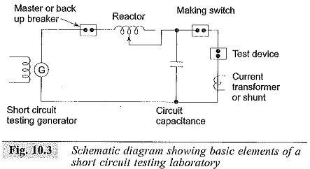
(b) Direct Testing in Short Circuit Test Laboratories: In order to test the circuit breakers at different voltages and at different short circuit currents, short circuit laboratories are provided. The schematic layout of a short circuit testing laboratory is given in Fig. 10.3. It consists of a short circuit generator in association with a master circuit breaker, resistors, reactors and measuring devices. A make switch initiates the short circuit and the master circuit breaker isolates the test device from the source at the end of a predetermined time set on a test sequence controller. Also, the master circuit breaker can be tripped if the test device fails to operate properly. Short circuit generators with induction motors as prime movers are also available.
(c) Synthetic Testing of Circuit Breakers: Due to very high interrupting capacities of High Voltage Test on Circuit Breaker and Isolators, it is not economical to have a single source to provide the required short circuit and the rated voltage. Hence, the effect of a short circuit is obtained as regards to the intensity of the current and the recovery voltage as a combination of the effects of two sources, one of which supplies the a.c. current and the other the high voltage.
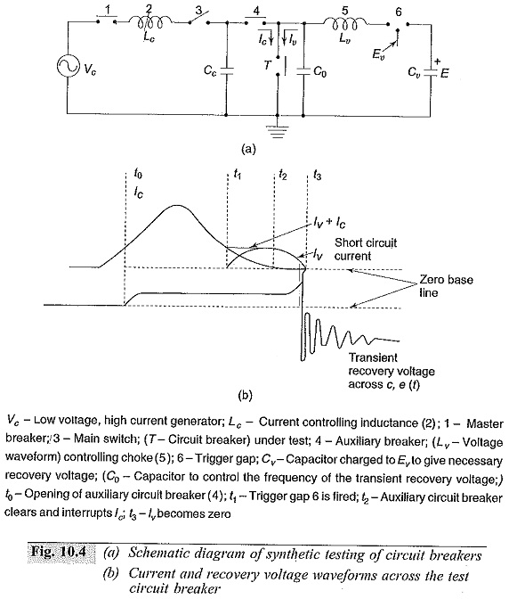
In the initial period of the short circuit test, the a.c. current source supplies the heavy current at a low voltage, and then the recovery voltage is simulated by a source of comparatively high voltage of small current capacity. A schematic diagram of a synthetic testing station is shown in Fig. 10.4.
With the auxiliary breaker (3) and the test breaker (T) closed, the closing of the making switch (1) causes the current to flow in the test circuit breaker. At some instant say to, the test circuit breaker (T) begins to operate and the master circuit breaker (T) becomes ready to clear the generator circuit. At some times t1, just before the zero of the generator current, the trigger gap (6) closes and the higher frequency current from the discharging capacitor Cv also flows through the arc. At time t2, when the generator current is zero, the circuit breaker (1) clears that circuit, leaving only the current from Cv which has the required rate of change of current at its zero flowing in the test circuit breaker. At the zero of this current, full test voltage will be available. The closing of gap (6) would be a little clarity at current zeros. It is important to see that the high-current source is disconnected and a high-voltage source applied with absolute precision (by means of an auxiliary circuit breaker) at the instant of circuit breaking.
(d) Composite Testing: In this method, the breaker is first tested for its rated breaking capacity at a reduced voltage and afterwards for rated voltage at a low current. This method does not give a proper estimate of the breaker
(e) Unit Testing: When large circuit breakers of very high voltage rating (220 kV and above) are to be tested and where more than one break is provided per pole, the breaker is tested for one break at its rated current and the estimated voltage and gap may not be identical and the voltage distribution along several breaks may be uneven. Hence, certain uncertainty prevails in the testing of one break.
(f) Testing Procedure: The High Voltage Test on Circuit Breaker and Isolators are tested for, their (i) breaking capacity B, and (ii) making capacity M. The circuit breaker, after the calibration of the short circuit generator, is tested for the following duty cycle.
The power factor in these tests is generally between 0.15 and 0.3. The numeral 3 in the above duty cycle indicates the time interval in minutes between the tests.
(g) Asymmetrical Tests: One test cycle is repeated for the asymmetrical breaking capacity in which the d.c. component at the instant of contact separation is not less than 50% of the a.c. component.


