High Voltage Test on Radio:
Many electrical apparatuses like transformers, line conductors, rotating machines, etc. produce unwanted electrical signals in the radio and high frequency (television band, microwave bands, etc.) ranges. These signals arise due to corona discharges in air, internal or partial discharges in the insulation, sparking at commutators and brush gear in rotating machines, etc. It is important to see that the noise voltages generated in the radio and other transmission bands are limited to acceptable levels, and hence the High Voltage Test on Radio interference voltage measurements are of importance. It has been found that the surface conditions of the overhead conductors subjected to high voltage stresses and varying atmospheric conditions greatly influence the magnitude of the noise voltage produced. In case of solid insulators, the bonding between the porcelain and the metal pin, the binding of high voltage conductor and the insulator surface, and the surface pollution were found to be the sources of this noise.
Measurements of Radio Interference Voltage:
The noise generated in the radio frequency band as a result of corona or partial discharges in high voltage power apparatus may be measured
- by the radio frequency line to ground voltage known as the radio influence voltage or RIV, and
- as an interfering field by means of an antenna known as the radiated radio interference voltage or RI.
Normally, the tests and measurements done in the laboratories are RIV measurements, whereas field investigations with portable radio receivers are RI measurements.
A High Voltage Test on Radio noise meter used in the laboratory consists of a portable radio receiver with a local oscillator, a radio frequency amplifier, a mixer, an intermediate frequency amplifier, and a detector similar to that of a standard radio receiver and operates in the frequency range 150 kHz to 30 MHz. In addition, the High Voltage Test on Radio noise meter has multi-input circuits to accommodate a number of pick-up devices, attenuators, calibrators, and output circuits containing special detectors and meters. The detector circuit consists of a diode detector in series with a series resistance Rs, charging a parallel R-C circuit. The detector circuit is provided with a measuring device to measure either (a) the average value, (b) the peak value, or (c) quasi-peak value (the quasi-peak value of the impulse noise is equal to the rms value of the sine wave at the centre frequency of the pass band which produces the same deflection in the meter scale as that of the impulse). The voltmeter provided at the end of the detector has an input impedance of 50 to 75Ω.
Test Circuits for the Measurements:
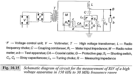
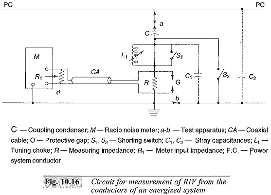
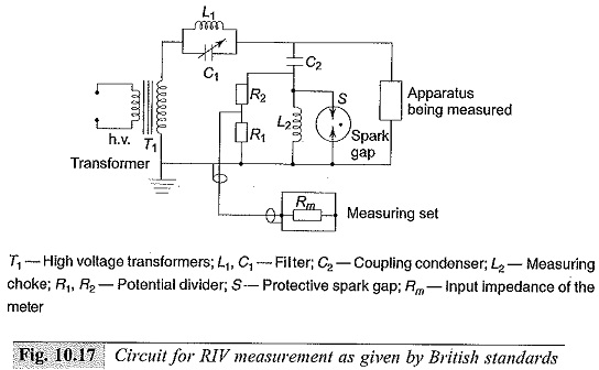
The schematic circuits used for RIV measurements are shown in Figs 10.15, 10.16 and 10.17. The RIV meter is first calibrated as per standards. The important components of the circuits are:
- The ratio frequency choke to limit the loss of the RIV voltage and to conduct energy from the sample. The choke itself should be free from noise, and its impedance should be less than 1500 Ω.
- The coupling capacitor C(< 0.001 μF); it should be free from noise in the operating range and the resistance of R should be equal to 800 Ω. The value indicated by the meter gives the conducted High Voltage Test on Radio noise from the test sample.
- Coaxial cable (CA): A coaxial cable of characteristic impedance 185 Ω shall be connected between the resistance R and the radio noise meter.
When the High Voltage Test on Radio noise meter measurements are stated, the information regarding the specifications of the meter used, the frequency range of measurements, the band pass characteristics, and the open circuit and the detector characteristics have to be mentioned.
Nowadays, for transmission systems of 400 kV and above, High Voltage Test on Radio noise voltages are of importance, and corrective measures are to be adopted for various apparatus and hardware to minimize the radio and television band noise.


