Conversion of Hybrid Parameters in Transistor Three Configurations:
Some transistor manufacturers provide only the four CE hybrid parameters while others provide CB hybrid parameters. Sometimes, for a specific purpose, it becomes necessary to convert one set of h parameters in one configuration to another set in another configuration. The conversion formulas can be obtained using the definitions of the parameters involved and Kirchhoff’s laws.
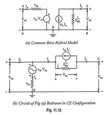
For example, let us convert common-emitter h parameters to the common-base h parameters. For this purpose first the CB hybrid model is drawn as shown in Fig. 11.12 (a) and then it is redrawn in CE configuration, as shown in Fig. 11.12 (b). The latter corresponds in every detail to the former except that the emitter terminal E is made common to the input and output ports.
By definitions
If Ib = 0, then Ic = -Ie, and the current I in hob in Fig. 11.12 (b) is I = (1 + hfb) Ie = hob Vbc
Applying Kirchhoff’s voltage law to the output mesh of Fig. 11.12 (b) we have
Combining the above two equations we have
Thus
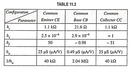
This is an exact expression. The simpler approximate formula is obtained by noting that, for typical values given in Table 11.3 hrb << 1 and hobhib << (1 + hfb)
So
By definition
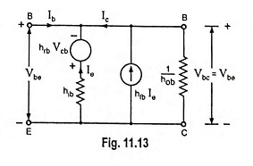
If terminals C and E are connected together in Fig. 11.12 (b), we have circuit shown in Fig. 11.13.
From Fig. 11.13, we see that Vcb = -Vbc = – Vbe
Applying Kirchhoff’s voltage law to the left-hand mesh, we have
Combining the above two equations we have
Applying Kirchhoff’s current law to node B in Fig. 11.13, we have
Thus
This is an exact expression. Since hrb << 1 and hob hib << (1 + hfb), so the above equation is reduced to
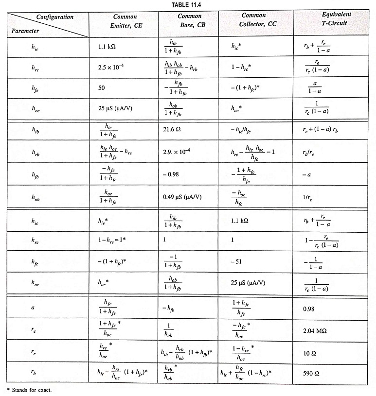
Approximate conversion formulas for transistor parameters are given in Table 11.4.


