Hybrid Stepper Motor Construction and Working:
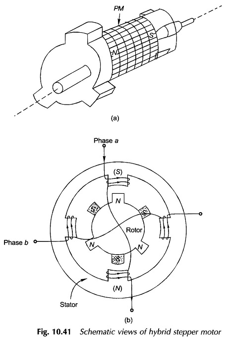
This is in fact a PM stepper motor with constructional features of toothed and stacked rotor adopted from the variable-reluctance motor. The stator has only one set of winding-excited poles which interact with the two rotor stacks. The permanent magnet is placed axially along the rotor in form of an annular cylinder over the motor shaft. The stacks at each end of the rotor are toothed. So all the teeth on the stack at one of the rotor acquire the same polarity while all the teeth of the stack at the other end of the rotor acquire the opposite polarity. The two sets of teeth are displaced from each other by one half of the tooth pitch (also called pole pitch). Hybrid Stepper Motor Construction and Working details are brought out by Fig. 10.41(a) and (b) for the case of three teeth on each stack so that tooth pitch γt = 360°/3 = 120°. This motor has a 2-phase, 4-pole stator.
In the Hybrid Stepper Motor Construction and Working, Now consider that the stator phase ‘a’ is excited such that the top stator pole acquires north polarity while the bottom stator pole acquires south polarity. As a result of the nearest tooth of the front stack (assumed to be of north polarity) is pulled into locking position with the stator south pole (top) and the diametrically opposite tooth of the rear stack (south polarity) is simultaneously locked into the stator north pole (bottom). The repulsive forces on the remaining two front stack teeth balance out as these are symmetrically located w.r.t. the bottom stator pole and so do the repulsive forces due to the top stator pole on the remaining two rear stack teeth. This rotor position is thus a stable position with net torque on rotor being zero.
If the excitation is shifted from phase a to phase b such that right-hand pole becomes south and left-hand pole becomes north, this would cause the rotor to turn anticlockwise by γt / 4 = 30° into the new locking position. The rotor will turn clockwise by 30° if the phase b were oppositely excited.
If the stator excitation were to be removed, the rotor will continue to remain locked into the same position as it is prevented to move in either direction by torque because of the permanent magnet excitation. This fact is in favour of hybrid (also PM) motors. Compared to PM motor finers steps for better resolution are easily obtained in hybrid motor by increasing the number of stack teeth and also by adding additional stack pairs on the rotor for example for a seven teeth stack the steps size is (3600/7)/4 = (124/7)°. Also compared to variable-reluctance motor a hybrid motor requires less stator excitation current because of the PM excited rotor.
Half stepping can be achieved in a hybrid motor by exciting phase a and then exciting phase b before switching off the excitation of phase ‘a’ and so on. In fact any fractional step can be obtained by suitably proportioning the excitation of the two phases. Such stepping is known as microstepping.
Typical step angles for Hybrid Stepper Motor Construction and Working are 15°, 7.5°, 2° and 0.72°. The choice of the angle depends upon the angular resolution required for application.
Torque vs Pulses Rate for Stepper Motor:
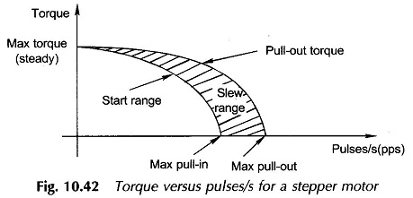
As the stepping rate is increased, the rotor has less time to drive the load from one position to the next as the stator-winding current pattern is shifted. Beyond a certain pulsing rate [(pulse/s) = pps] the rotor cannot follow the command and would begin to miss pulses. The start range as shown in Fig. 10.42 is that in which the load position follows the pulses without losing steps. The slew-range is one in which the load velocity follows the pulse rate without losing a step, but cannot start, stop or reverse on command. Obviously the maximum slew rate would increase as the load is lightened. Typical variable-reluctance motors can operate at maximum position response rates up to 1200 pps.
Step skipping may also occur if motor oscillation amplitude about the locking position is too large.

