Hysteresis Loss and Eddy Current Loss in Transformer:
When a magnetic material undergoes cyclic magnetization, two kinds of power losses occur in it Hysteresis Loss and Eddy Current Loss in Transformer which together are known as Core Loss in transformer. The Core Loss in transformer is important in determining heating, temperature rise, rating and efficiency of transformers, machines and other ac run magnetic devices.
Hysteresis Loss Formula:
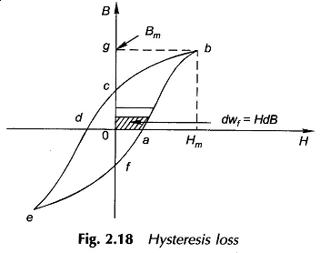
Figure 2.18 shows a typical hysteresis loop of a ferromagnetic material. As the mmf is increased from zero to its maximum value, the energy stored in the field per unit volume of material is
As H is now reduced to zero, dB being negative, the energy is given out by the magnetic field (from the exciting coil back to the voltage source) and has a value![]()
The net energy unrecovered in the process is area of abc0 which is lost irretrievably in the form of heat and is called the Hysteresis Loss in Transformer. The total hysteresis loss in one cycle is easily seen to be the area of the complete loop (abcdefa) and let it be indicated as wh (hysteresis loss/unit volume). Then hysteresis loss in volume V of material when operated at fHz is
In order to avoid the need for computation of the loop area, Steinmetz gave an empirical formula for computation of the hystersis loss based on experimental studies according to which
where kh is a characteristic constant of the core material, Bm is the maximum flux density and n, called the Steinmetz exponent, may vary from 1.5 to 2.5 depending upon the material and is often taken as 1.6.
Eddy Current Loss Equation:
When a magnetic core carries a time-varying flux, voltages are induced in all possible paths enclosing the flux. The result is the production of circulating currents in the core (all magnetic materials are conductors). These currents are known as eddy-currents and have power loss (i2R) associated with them called eddy-current loss. This loss, of course, depends upon the resistivity of the material and lengths of the paths of circulating currents for a given cross-section. Higher resistivity and longer paths increase the effective resistance offered by the material to induce voltages resulting in reduction of eddy-current loss.
High resistivity is achieved by adding silicon to steel and hence silicon steel is used for cores conducting alternating flux. Dividing up the material into thin laminations along the flow of flux, with each lamination lightly insulated (varnish is generally used) from the adjoining ones, increases the path length of the circulating currents with consequent reduction in eddy-current loss. The Hysteresis Loss and Eddy Current Loss in fact can be shown to depend upon the square of lamination thickness. The lamination thickness usually varies from 0.3 to 5 mm for electromagnetic devices used in power systems and from about 0.01 to 0.5 mm for devices used in electronic applications where low Core Loss in transformer is desired.
The eddy current loss can by expressed by the empirical formula
d being the thickness of lamination and ρ the resistivity of material.
Hysteresis Eddy Current Loss is only an academic exercise to split the core loss into its two components. The Hysteresis Loss in Transformer and Eddy Current Loss in Transformer in fact arises from two types of flux variations:
- flux that has a fixed axis and varies sinusoidally with time as in transformers (this is the type visualized in the above discussion),
- flux density is constant but the flux axis rotates.
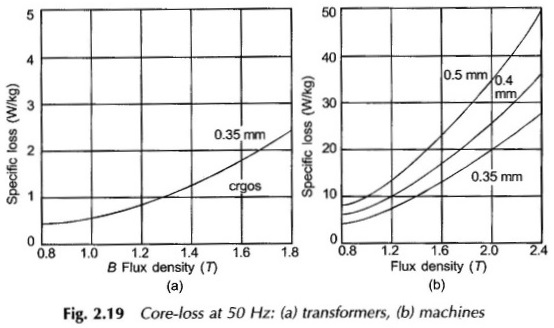
Actually in ac machines as well as in armature of dc machines the flux variation comprises both these types occurring simultaneously. Hysteresis Loss and Eddy Current Loss is measured experimentally on material specimen and presented graphically. Typical values of the specific core loss (W/kg of material) are displayed in Figs 2.19 (a) and (b) for cold-rolled grain-oriented (crgos) steel. It is easy to see from these figures that for reasons mentioned above specific core loss is much higher in machines than in transformers.


