Impedance Coupled Transistor Amplifier:
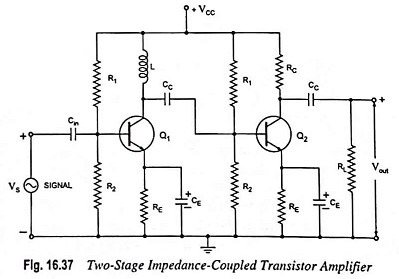
A two-stage impedance coupled transistor amplifier using N-P-N transistors in CE configuration is shown in Fig. 16.37. The only difference between this circuit and R-C coupled transistor amplifier circuit is that collector resistance RC of first transistor has been replaced by an inductor L. The inductor turns are wound on a closed iron core and shielded so that the magnetic field of the coupling inductor does not affect the signal.
The operation of the circuit is the same as that of the R-C coupled circuit as we discussed already.
Circuit Analysis:
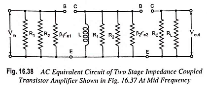
The ac equivalent circuit at mid frequency of the cascaded amplifier given in Fig. 16.38. Because of mid frequency range, all the capacitances have been considered as short circuit.
Voltage gain of first stage,
For XL ≫ R1 || R2 || β2r′e2
Voltage gain of second stage,
and overall voltage gain,


