Insulation Coordination in High Voltage:
Insulation Coordination in High Voltage – Electric power supply should ensure reliability and continuity to the utility concerns. Hence, the power lines and sub-stations are to be operated and protected against overvoltages such that the number of failures are as few as possible. At the same time, the cost involved in the design, installation, and operation of the protective devices should not be too high. Hence, a gradation of system insulation and protective device operation is to be followed, keeping in view the importance of the various equipment involved.
Generally, sub-stations contain transformers, switchgear, and other valuable equipment with non-self restoring Insulation Coordination in High Voltage, which have to be protected against failures and internal destruction. For other apparatus, which contain self-restoring insulation, like string insulators, they may be allowed to flashover in air. But the flashovers should be kept to a minimum so that the system disturbances are the least. Hence, lightning and switching surge protection requires establishment of protective voltage levels called shunt protection levels
The lightning impulse withstand level known as the Basic Impulse Level (BIL) is established for each system nominal voltage for different apparatus. Various equipment and their component parts should have their BIL above the system protective level, by a suitable margin. This margin is usually determined with respect to air insulation by statistical methods. For non-self-restoring Insulation Coordination in High Voltage like the transformer insulation, the margin limit is fixed using conventional methods.
For system voltages below 400 kV, the switching surges are not of importance. If the BIL is chosen correctly, relative to the prevailing protective level, the equipment will have an adequate switching surge level. For higher system voltages, since the switching surges are of higher magnitude compared to the lightning overvoltages, switching surge magnitudes are of importance and the following criterion is to be adopted.
1.The flashover voltage of a protective derive is chosen such that it will not operate for switching overvoltages and other power frequency and its harmonic overvoltages. But other long duration overvoltages, namely, sustained overvoltage due to faults and even the above-mentioned overvoltages may sometimes cause thermal overloading due to leakage Therefore, the BIL has to be higher.
2.For EHV systems, it may be economical to use a protective device for limiting the overvoltages due to lightning as well as switching surges to a particular level. At present, there are surge arresters which operate for both types of overvoltages mentioned above. In such cases, it is preferable to assign to each protected equipment a Switching Impulse Level (SIL), so that there is a small margin above the controlled switching surge level, so that the surge diverters operate on switching surges, only when the controlling devices fail. Normally, only rod gaps and lightning arresters are used as protective devices for protection, and their characteristics are considered here.
The ideal requirements of a protective device connected in parallel or in shunt are:
- It should not usually flashover for power frequency overvoltages.
- The volt-time characteristics of the device must lie below the withstand voltage of the protected apparatus or insulation. The marginal difference between the above two should be adequate to allow for the effects of distance, polarity, atmospheric conditions, changes in the characteristics of the devices due to ageing, etc.
- It should be capable of discharging high energies contained in surges and recover insulation strength quickly.
- It should not allow power frequency follow-on current to flow.
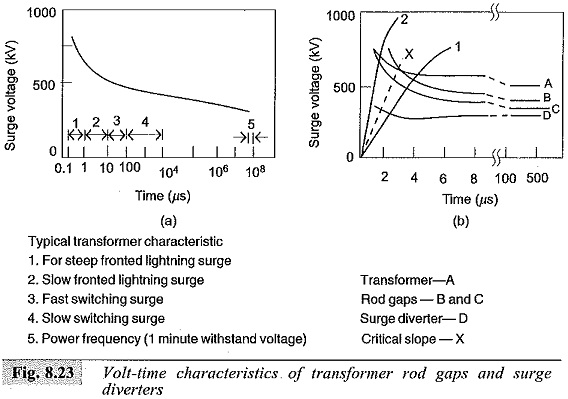
The behaviour of shunt connected protective devices like rod gaps and surge diverters along with transformer Insulation Coordination in High Voltage is given in Fig. 8.23. In Fig. 8.23a the transformer insulation strength is given as a volt-time characteristic. Figure 8.23b gives the relative insulation strengths of the transformer (curve A), rod gaps (curves B and C), and that of a lightning arrester (curve D).
A lightning arrester protects the transformer insulation in the entire time region. The rod gap protects the transformer insulation, only if the rate of rise of surge is less than the critical slope (curve X). Thus, if the surge voltage rise is as shown by curve 1, rod gap flashes and protects the transformer, if the surge voltage rise follows curve 2, only the surge diverter can protect the transformer insulation.
Rod gaps are simple and cheap devices but do not meet all the requirements of a protective device. Moreover, their flashover characteristics depend on the atmospheric conditions, polarity of the wave, and waveshape. Also, it may give rise to very steep impulse waves on the transformer windings as chopped waves, because no current limiting resistance is used. Chopped impulse waves may lead to the destruction of the transformer turn to turn Insulation Coordination in High Voltage. But still, rod gaps provide reasonable protection where lightning surge levels are low, and steep fronted surges are controlled by overhead ground wires.
