Interfacing Dip Switch:
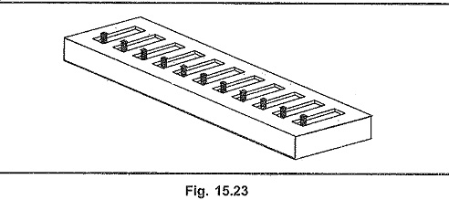
A series of tiny switches built into circuit board and the housing for which has a same shape as chip are known as DIP switches. The Fig. 15.23 shows the Interfacing Dip Switch housing with 11 switches. DIP switches enable you to configure a circuit board for a particular type of computer or application. The installation instructions should tell you how to set the switches. DIP switches are always toggle switches, which means they have two possible positions either ON or OFF.
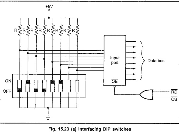
The DIP switch is always interfaced through the input port. Thus microprocessor can read the DIP switch settings by reading the contents of the input port. The Fig. 15.23 (a) shows the interfacing diagram.
When switch is ON, data input is 0 and when switch is off data input is 1.
Thumb Wheel Switches:
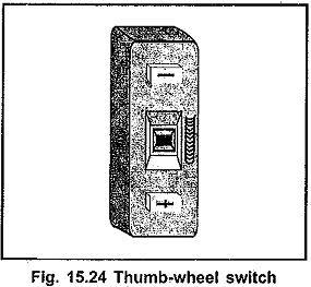
Thumb Wheel switches are the mechanical switches used to provide numerical input to the microprocessor based systems. Each thumb-wheel represents one digit decimal input, i.e. 0-9. The Fig. 15.24 shows the thumbwheel switch. Each switch is provided with a wheel. This wheel can be rotated by a thumb to change the input number hence the name.
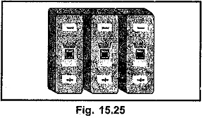
Now-a-days instead of wheel, the thumb-wheel switch is provided with two push buttons. One push button to increment the numeric value and other to decrement the numeric value as shown in the Fig. 15.25.
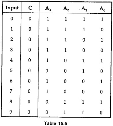
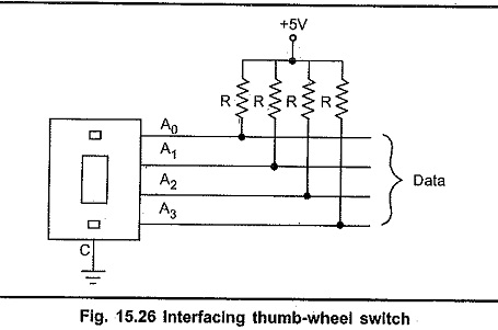
Each thumbwheel has four data pins and one control input (c). Four data pins represent input number in binary form. The Table 15.5 shows the information on the data pins for all numeric inputs. It is assumed that the control input is connected to ground and each data line is tied to VCC through register as shown in the Fig. 15.26.
Like DIP switches, thumb-wheel swtiches are also interfaced through input ports. Each thumb-wheel requires four input pins Therefore, we can interface two thumb-wheel switches using one 8-bit input port.
