Interrupt Structure of 8086:
An Interrupt Structure of 8086 can come from any one the three sources :
- External signal
- Special Instruction in the program
- Condition produced by instruction
External Signal (Hardware Interrupt):
An 8086 can get interrupt from an external signal applied to the nonmaskable interrupt (NMI) input pin; or the interrupt (INTR) input pin.
Special Instruction:
Interrupt Structure of 8086 supports a special instruction, INT to execute special program. At the end of the interrupt service routine, execution is usually returned to the interrupted program.
Condition Produced by Instruction:
An 8086 is interrupted by some condition produced in the 8086 by the execution of an instruction. For example divide by zero : Program execution will automatically be interrupted if you attempt to divide an operand by zero.
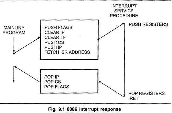
At the end of each instruction cycle 8086 Interrupts checks to see if there is any interrupt request. If so, 8086 responds to the interrupt by performing series of actions (Refer Fig. 9.1).
- It decrements stack pointer by 2 and pushes the flag register on the stack..
- It disables the INTR interrupt input by clearing the interrupt flag in the flag
- It resets the trap flag in the flag register.
- It decrements stack pointer by 2 and pushes the current code segment register contents on the stack.
- It decrements stack pointer by 2 and pushes the current instruction pointer contents on the stack.
- It does an indirect far jump at the start of the procedure by loading the CS and IP values for the start of the interrupt service routine (ISR).
An IRET instruction at the end of the interrupt service procedure returns execution to the main program.
Interrupt Vector Table 8086:
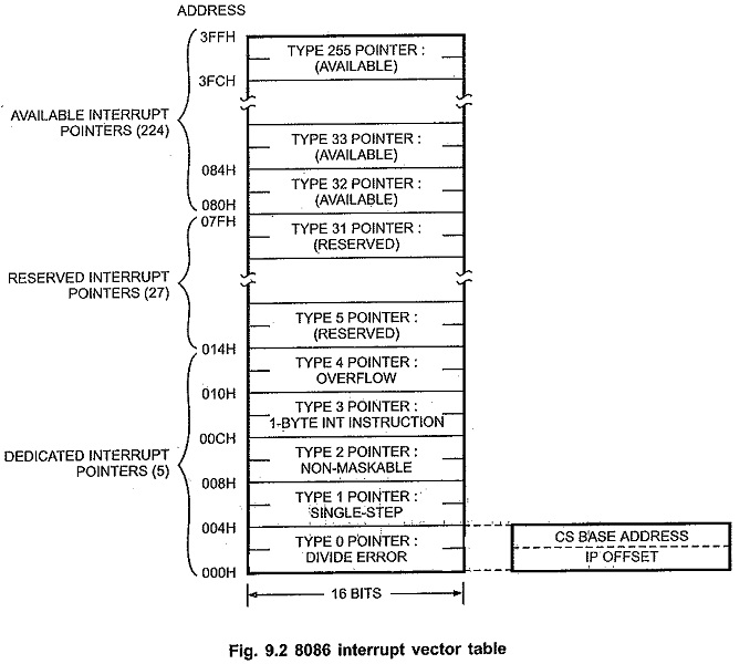
Now the question is “How to get the values of CS and IP register ?” The 8086 gets the new values of CS and IP register from four memory addresses. When it responds to an interrupt, the 8686 goes to memory locations to get the CS and IP values for the start of the interrupt service routine. In an Interrupt Structure of 8086 system the first 1 Kbyte of memory from 00000H to 003FFH is reserved for storing the starting addresses of interrupt service routines. This block of memory is often called the Interrupt Vector Table in 8086 or the interrupt pointer table. Since 4 bytes are required to store the CS and IP values for each interrupt service procedure, the table can hold the starting addresses for 256 interrupt service routines. Fig. 9.2 shows how the 256 interrupt pointers are arranged in the memory table.
Each interrupt type is given a number between 0 to 255 and the address of each interrupt js found by multiplying the type by 4 e.g. for type 11, interrupt address is 11 x 4 = 4410= 0002CH
Only first five types have explicit definitions such as divide by zero and non maskable interrupt. The next 27 interrupt types, from 5 to 31, are reserved by Intel for use in future microprocessors. The upper 224 interrupt types, from 32 to 255, are available for user for hardware or software interrupts.
When the 8086 responds to an interrupt, it automatically goes to the specified location in the Interrupt Vector Table in 8086 to get the starting address of interrupt service routine. So user has to load these starting addresses for different routines at the start of the program.

