Negative Feedback Op Amp:
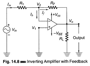
Negative Feedback Op Amp – The Inverting Amplifier configuration is shown in Fig. 14.8. The input signal is applied to the inverting terminal. The amplified inverted output is fed back to the inverting input through the resistor RF. The signal fed back is proportional to the output voltage, feedback takes place through RF connected between the output and the inverting terminal of the amplifier. Phase inversion through the amplifier ensure that the feedback is negative.
In Fig. 14.8, the non-inverting terminal is grounded and the input signal is applied to the inverting terminal through a resistance R1. The difference input voltage is ideally zero, since the voltage at the inverting terminal (V2) is approximately equal to that at the non-inverting terminal (V1). In other words, the inverting terminal voltage V2 is approximately at ground potential. Therefore, the inverting terminal is said to be at virtual ground. The closed loop gain of the inverting amplifier can be computed as follows.
Referring to the circuit, since Ib is negligible Iin ≡ If
Therefore
But
Hence
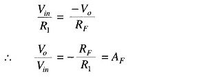
Therefore, closed loop voltage gain for an inverting amplifier is,


